
TM 5-3805-293-23-4
0216
INSTALLATION CONTINUED
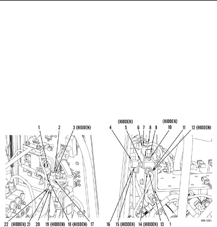
3. Install new O-ring (Figure 4, Item 18) and elbow (Figure 4, Item 17) on steering backup valve (Figure 4,
Item 1).
4. Install new O-ring (Figure 4, Item 19) and connect hydraulic tube (Figure 4, Item 20) to fitting (Figure 4,
Item 12).
5. Install new O-ring (Figure 4, Item 21) and fitting (Figure 4, Item 22) on steering backup valve (Figure 4, Item 1).
6. Install new O-ring (Figure 4, Item 12) and connect hydraulic tube (Figure 4, Item 11) to fitting (Figure 4,
Item 4).
7. Install new O-ring (Figure 4, Item 14) and fitting (Figure 4, Item 13) on steering backup valve (Figure 4, Item 1).
8. Install new O-ring (Figure 4, Item 15) and connect hydraulic tube (Figure 4, Item 16) to elbow (Figure 4,
Item 4).
9. Install new O-ring (Figure 4, Item 5) and elbow (Figure 4, Item 4) on steering backup valve (Figure 4, Item 1).
10. Install new O-ring (Figure 4, Item 3) and connect hydraulic tube (Figure 4, Item 2) to elbow (Figure 4, Item 17).
11. Install six new O-rings (Figure 4, Item 10) and two cartridges (Figure 4, Item 9) on steering backup valve
(Figure 4, Item 1). Torque to 37 lb-ft (50 Nm).
12. Install two sleeves (Figure 4, Item 6), washers (Figure 4, Item 7), and locknuts (Figure 4, Item 8) on steering
backup valve (Figure 4, Item 1). Torque to 115 lb-in. (13 Nm).
Figure 4. Hydraulic Line Connections.
0216

