
TM 5-3805-293-23-4
0210
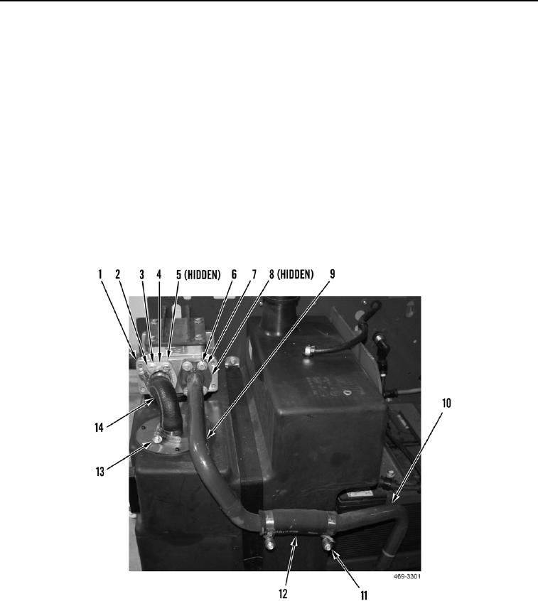
INSTALLATION CONTINUED
2. Loosely install hose (Figure 3, Item 12) and two clamps (Figure 3, Item 11) on two tubes (Figure 3, Items 9
and 10).
3. Install new O-ring (Figure 3, Item 8) on tube assembly (Figure 3, Item 9).
4. Install tube assembly (Figure 3, Item 9), four washers (Figure 3, Item 7), and bolts (Figure 3, Item 6) on
hydraulic filter base (Figure 3, Item 1).
5. Tighten two clamps (Figure 3, Item 11) on hose (Figure 3, Item 12).
6. Install new O-ring (Figure 3, Item 5) on tube assembly (Figure 3, Item 4).
7. Install tube assembly (Figure 3, Item 4), four washers (Figure 3, Item 3), and bolts (Figure 3, Item 2) on
hydraulic filter base (Figure 3, Item 1).
8. Install hose (Figure 3, Item 14) and two clamps (Figure 3, Item 13).
N OT E
Engine enclosure removed in Figure 3 for clarity.
Figure 3. Return Hydraulic Filter.
0210
END OF TASK

