
TM 5-3805-293-23-4
0174
CLEANING AND INSPECTION
000174
Clean and inspect all components IAW Mechanical General Maintenance Instructions (WP 0346).
END OF TASK
INSTALLATION
000174
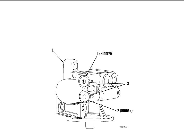
1. Install two new O-rings (Figure 4, Item 2) and plugs (Figure 4, Item 3) on filter base (Figure 4, Item 1).
Figure 4. Filter Base Plugs.
0174
N OT E
Install lines as tagged during removal.
2. Install three resilient mounts (Figure 5, Item 9), filter base (Figure 5, Item 2), spacer (Figure 5, Item 10), resil-
ient mount (Figure 5, Item 9), two washers (Figure 5, Item 8) and bolt (Figure 5, Item 7) on hydraulic service
pack (Figure 5, Item 11).
3. Install two spacers (Figure 5, Item 16), resilient mounts (Figure 5, Item 9), four washers (Figure 5, Item 8) and
two bolts (Figure 5, Item 17) on filter base (Figure 5, Item 2).
N OT E
Install fitting as noted during removal.
4. Install two new O-rings (Figure 5, Item 6) and fitting (Figure 5, Item 12) on filter base (Figure 5, Item 2),
5. Install new O-ring (Figure 5, Item 5), remove cap, and connect fuel line (Figure 5, Item 4) to filter base
(Figure 5, Item 2).
6. Install new O-ring (Figure 5, Item 14), remove cap, and connect fuel line (Figure 5, Item 3) to filter base
(Figure 5, Item 2).
7. Connect harness connector (Figure 5, Item 15) to fuel injection priming pump (Figure 5, Item 13).
8. Apply a light coating of clean fuel to seal of new primary fuel filter (Figure 5, Item 1).

