
TM 5-3805-293-23-4
0174
REMOVAL
000174
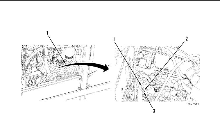
1. Loosen bolt (Figure 1, Item 3) and remove drain hose (Figure 1, Item 1) from clip (Figure 1, Item 2).
Figure 1. Drain Hose.
0174
2. Open drain valve (Figure 2, Item 21). Drain fuel into a suitable container.
3. Remove tiedown strap (Figure 2, Item 19), tube (Figure 2, Item 20) and drain valve (Figure 2, Item 21) from
water separator (Figure 2, Item 22).
N OT E
Tag and mark lines to aid in installation.
4. Remove water separator (Figure 2, Item 22) and O-ring (Figure 2, Item 18) from primary fuel filter (Figure 2,
Item 1). Discard O-ring.
5. Remove primary fuel filter (Figure 2, Item 1) from filter base (Figure 2, Item 2). Discard fuel filter.
6. Disconnect harness connector (Figure 2, Item 15) from fuel injection priming pump (Figure 2, Item 13).
7. Disconnect fuel line (Figure 2, Item 3) and remove O-ring (Figure 2, Item 5) from filter base (Figure 2, Item 1).
Install cap on fuel line. Discard O-ring.
8. Disconnect fuel line (Figure 2, Item 4) and remove O-ring (Figure 2, Item 14) from filter base (Figure 2, Item 2).
Install cap on fuel line. Discard O-ring.
N OT E
Note the direction of fitting to aid in installation.
9. Remove fitting (Figure 2, Item 12) and two O-rings (Figure 2, Item 6) from filter base (Figure 2, Item 2). Discard
O-rings.
10. Remove two bolts (Figure 2, Item 17), four washers (Figure 2, Item 8), two resilient mounts (Figure 2, Item 9)
and spacers (Figure 2, Item 16) from filter base (Figure 2, Item 2).
11. Remove bolt (Figure 2, Item 7), two washers (Figure 2, Item 8), resilient mount (Figure 2, Item 9), spacer
(Figure 2, Item 10), filter base (Figure 2, Item 2) and three resilient mounts (Figure 2, Item 9) from hydraulic
service pack (Figure 2, Item 11).

