
TM 5-3805-293-23-4
0171
INSTALLATION CONTINUED
N OT E
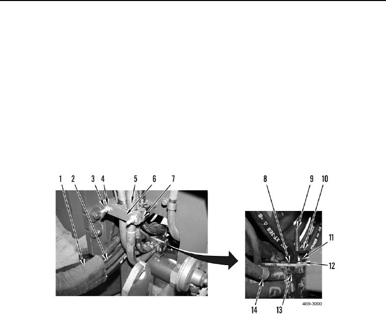
Position hoses on blocks as noted prior to removal.
11. Install two blocks (Figure 13, Item 13), plate (Figure 13, Item 8), washers (Figure 13, Item 12) and new
locknuts (Figure 13, Item 11) on studs (Figure 13, Item 9) and hose bundle (Figure 13, Items 2 and 5).
12. With assistance, position hose bundles (Figure 13, Items 2 and 5) as necessary and install block (Figure 13,
Item 10) on two studs (Figure 13, Item 9).
13. Return protective cover (Figure 13, Item 1) to its original installed position by pulling toward hose clamps
(Figure 13, Item 14) on left side of machine.
14. Install two blocks (Figure 13, Item 7), plate (Figure 13, Item 6), washers (Figure 13, Item 4) and new locknuts
(Figure 13, Item 3) to hose bundle (Figure 13, Item 5) on left side of machine.
15. Repeat two previous steps for right side of machine.
Figure 13. AWD Hydraulic Hose Assembly.
0171

