
TM 5-3805-293-23-4
0171
INSTALLATION CONTINUED
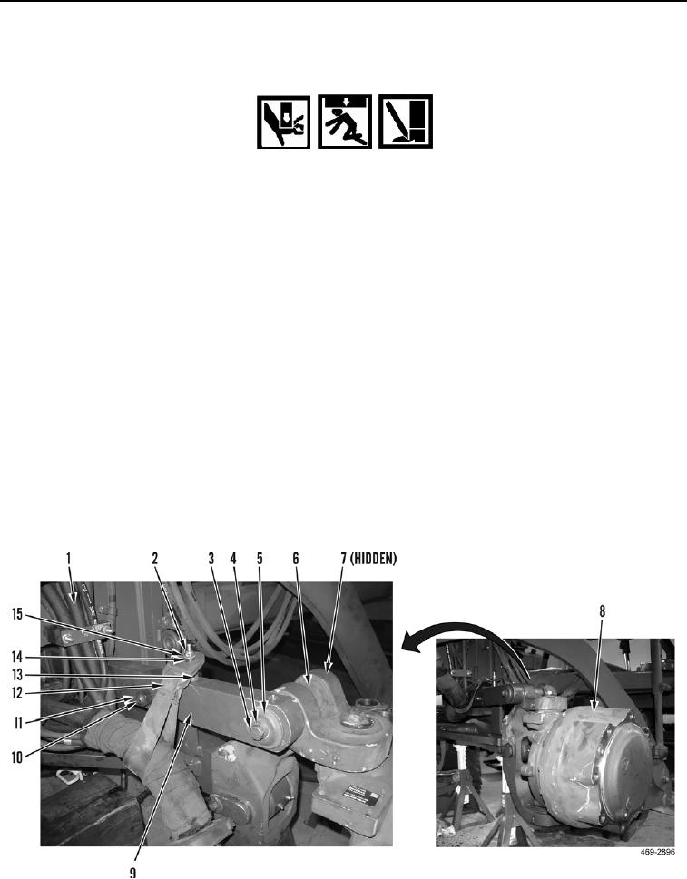
22. Attach sling and lifting device to wheel lean bar (Figure 16, item 9).
WARN I N G
Use extreme caution when handling heavy parts. Provide adequate support and use
assistance during procedure. Ensure any lifting device used is in good condition and of
suitable load capacity. Keep clear of heavy parts supported only by lifting device. Failure
to follow this warning may cause injury or death to personnel.
N OT E
Wheel lean bar weighs 110 lb (50 kg).
23. Using lifting device, position wheel lean bar (Figure 16, item 9) on machine.
24. Install sling and lifting device on left wheel lean arm assembly (Figure 16, Item 8).
25. Using lifting device, align wheel lean arm assembly (Figure 16, item 8) and wheel lean bar (Figure 16, Item 9).
26. Install spacer (Figure 16, Item 6), pin (Figure 16, Item 7), cap (Figure 16, Item 5), washer (Figure 16, Item 4),
and bolt (Figure 16, Item 3) on wheel lean arm assembly (Figure 16, Item 8) and wheel lean bar (Figure 16,
item 9). Torque to 148 lb-ft (200 Nm).
27. Install wheel lean lock bolt (Figure 16, Item 10) and nut (Figure 16, Item 11) on wheel lean bar (Figure 16,
Item 9). Hand tighten only.
28. Remove lifting device from wheel lean arm assembly (Figure 16, Item 8).
29. Remove sling and lifting device from wheel lean bar (Figure 16, Item 9).
30. Position two straps (Figure 16, Item 12) around hose bundles (Figure 16, Item 1) and install two spacers
(Figure 16, Item 13), spacers (Figure 16, Item 14), straps (Figure 16, Item 12), washers (Figure 16, Item 15),
and new lock nuts (Figure 16, Item 2) on wheel lean bar (Figure 16, Item 9).
Figure 16. Wheel Lean Bar.
0171

