
TM 5-3805-293-23-3
0147
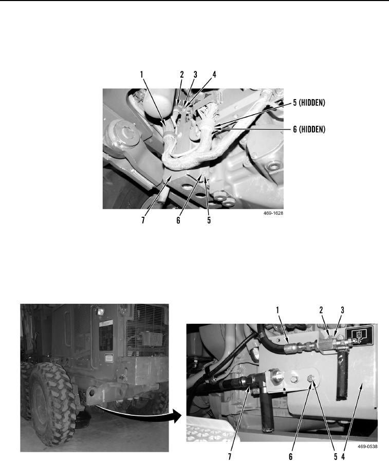
INSTALLATION CONTINUED
5. Install cover (Figure 5, Item 7), three washers (Figure 5, Item 5), and bolts (Figure 5, Item 6) on machine.
6. Install clamps (Figure 5, Item 2), two washers (Figure 5, Item 4), and bolts (Figure 5, Item 3) on wiring harness
(Figure 5, Item 1).
Figure 5. Wiring Harness Clamps and Cover.
0147
7. Position hose assembly (Figure 6, Item 7) on cover (Figure 6, Item 4). Install two washers (Figure 6, Item 6)
and bolts (Figure 6, Item 5) on hose assembly.
8. Position hose assembly (Figure 6, Item 1) on cover (Figure 6, Item 4). Install two washers (Figure 6, Item 3)
and bolts (Figure 6, Item 2) on hose assembly.
Figure 6. Hose Assemblies.
0147
END OF TASK