TM 5-3805-293-23-3
0120
INSTALLATION CONTINUED
5. Remove sling and lifting device from implement and steering pump.
WARN I N G
Hydraulic oil is very slippery. Immediately wipe up any spills. Failure to follow this warning
may result in injury to personnel.
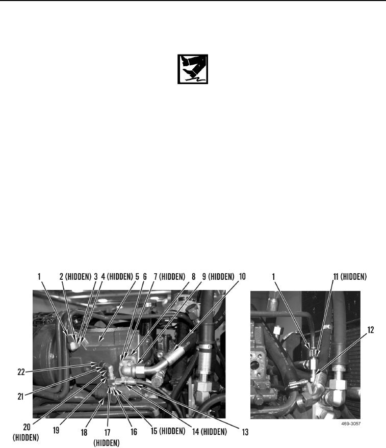
6. Install new O-ring (Figure 6, Item 15) and tee (Figure 6, Item 16) on pressure control valve (Figure 6, Item 18).
7. Install new O-ring (Figure 6, Item 17) and elbow (Figure 6, Item 19) on tee (Figure 6, Item 16).
8. Install new O-ring (Figure 6, Item 20), coupling (Figure 6, Item 21) and cap (Figure 6, Item 22) on elbow
(Figure 6, Item 19).
9. Install new O-ring (Figure 6, Item 7), elbow (Figure 6, Item 8) and four capscrews (Figure 6, Item 6) on
implement and steering pump (Figure 6, Item 5).
10. Install new O-ring (Figure 6, Item 9) and connect hose (Figure 6, Item 10) to implement and steering pump
(Figure 6, Item 5).
11. Install new O-ring (Figure 6, Item 4) and elbow (Figure 6, Item 3) on implement and steering pump (Figure 6,
Item 5).
12. Install two new O-rings (Figure 6, Item 11 and Item 2) and connect tube (Figure 6, Item 1) to manifold
(Figure 6, Item 12) and implement and steering pump (Figure 6, Item 5).
13. Install new O-ring (Figure 6, Item 14) and connect hose (Figure 6, Item 13) to tee (Figure 6, Item 16).
Figure 6. Implement and Steering Pump Hose.
0120
END OF TASK

