
TM 5-3805-293-23-3
0117
INSTALLATION
000117
N OT E
Install wiring harnesses as tagged at removal.
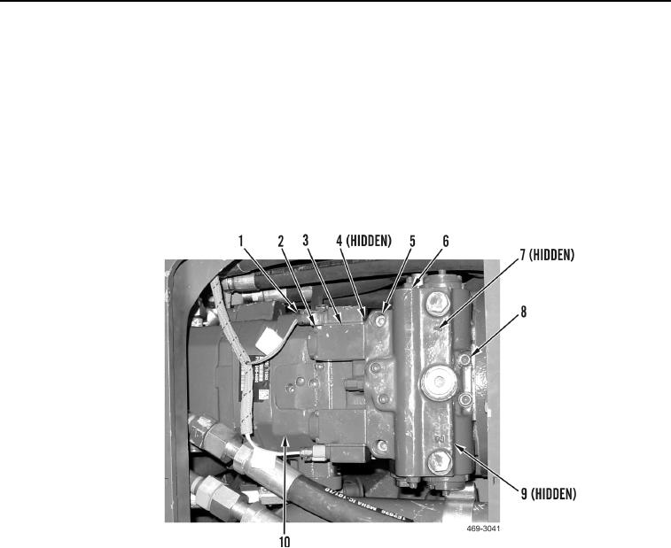
1. Install new O-ring (Figure 3, Item 9), eight new O-rings (Figure 3, Item 7), control valve (Figure 3, Item 6), two
bolts (Figure 3, Item 8), and bolts (Figure 3, Item 5), on AWD pump (Figure 3, Item 10).
2. Install two new O-rings (Figure 3, Item 4), solenoids (Figure 3, Item 3) and eight bolts (Figure 3, Item 2), on
control valve (Figure 3, Item 6).
3. Connect two wire harness connectors (Figure 3, Item 1) to solenoids (Figure 3, Item 3).
Figure 3. AWD Control Valve.
0117