TM 5-3805-293-23-3
0114
REMOVAL CONTINUED
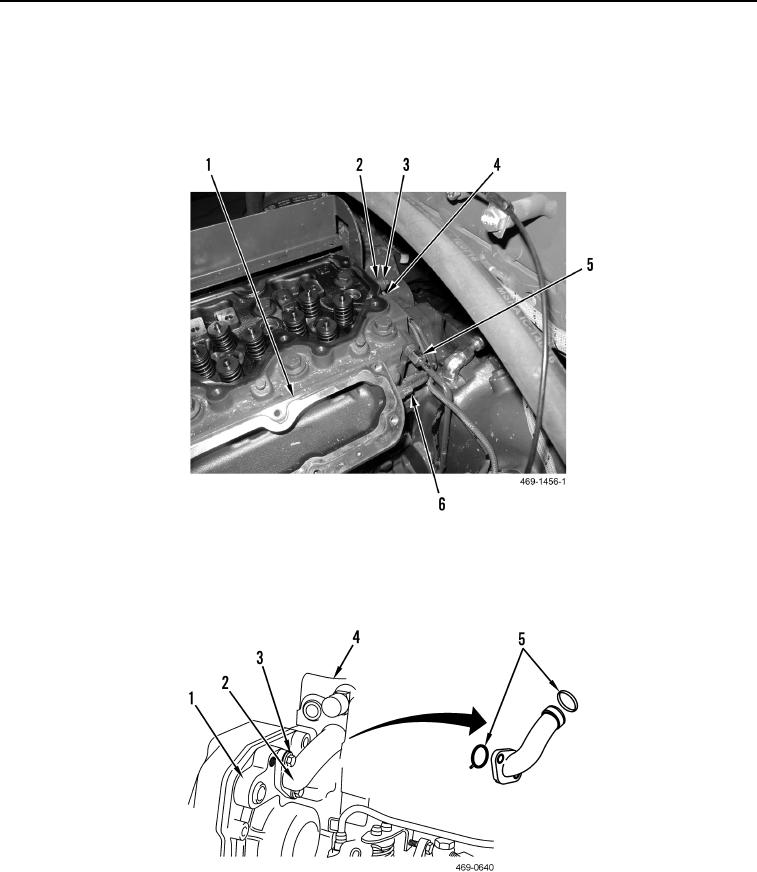
11. Remove oil line (Figure 5, Item 5) from cylinder head (Figure 5, Item 1).
12. Remove waste gate pressure tube assembly (Figure 5, Item 6) from cylinder head (Figure 5, Item 1).
13. Remove bolt (Figure 5, Item 3), clamp (Figure 5, Item 4), and spacer (Figure 5, Item 2) from cylinder head
(Figure 5, Item 1).
Figure 5. Oil and Waste Gate Pressure Lines.
0114
14. Remove two bolts (Figure 6, Item 3) and bypass tube assembly (Figure 6, Item 2) from front housing (Figure 6,
Item 1) and cylinder head (Figure 6, Item 4). Remove and discard two O-rings (Figure 6, Item 5) from bypass
tube.
Figure 6. Bypass Tube.
0114

