
TM 5-3805-293-23-3
0044
BRAKE CONTROL VALVE (SERVICE) CHECK CONTINUED
00044
N OT E
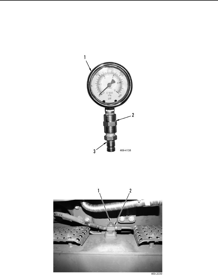
Apply sealing compound on pipe coupling and pressure gauge threads.
4. Assemble two 1,450 psi pressure gauges. Install pipe coupling (Figure 81, Item 2) and hose coupling (Figure
81, Item 3) on both pressure gauges (Figure 81, Item 1).
Figure 81. 1450 PSI Pressure Gauge.
0044
5. Remove plug (Figure 82, Item 1) from left service brake test port (Figure 82, Item 2). Install coupling, hose, and
gauge onto test port.
Figure 82. Left Service Brake Test Port.
0044