
TM 5-3805-293-23-3
0044
BRAKE CONTROL VALVE (SERVICE) CHECK CONTINUED
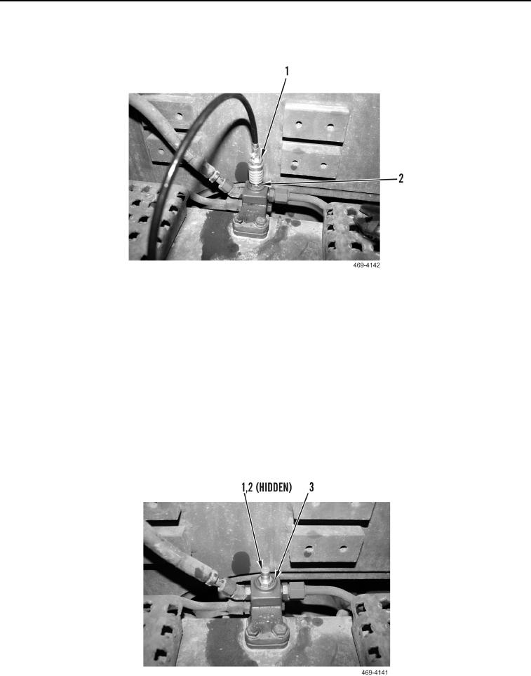
8. Install hose and gauge assembly (Figure 85, Item 1) on hose coupling (Figure 85, Item 2).
Figure 85. Test Hose.
0044
9. Repeat steps 5 through 8 for other side.
10. Start engine (TM 5-3805-293-10).
11. Depress brake pedal. Do not permit brake pedal to come up.
12. Shut off engine (TM 5-3805-293-10).
13. Monitor pressure. If service brake pressure drops more than 140 kPa (20 psi) after two minutes, the brake con-
trol valve must be inspected for leakage.
14. Release hydraulic system pressure, pump service brake pedal at intervals of one second, on and off, for at
least 110 applications.
15. Remove gauge and hose assembly (Figure 85, Item 1) from hose coupling (Figure 85, Item 2).
16. Remove hose coupling (Figure 86, Item 1) and O-ring (Figure 86, Item 2) from test port (Figure 86, Item 3).
Figure 86. Hose Coupling and Test Port.
0044