
TM 5-3805-293-23-3
0044
BRAKE ACCUMULATOR CHARGING VALVE TEST AND ADJUST CONTINUED
19. Pump service brake pedal until pressure in brake system decreases to cut-in pressure. The system will
recharge and pump will cut out at maximum pressure. Compare pressure readings on both pressure gauges.
The highest pressure is cut-out pressure. The maximum pressure is 2,300 50 psi (15,858 345 kPa).
20. If adjustment is necessary, perform following operation:
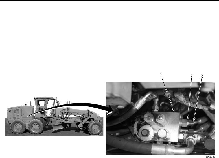
a. Loosen locknut (Figure 43, Item 2) on brake control manifold (Figure 43, Item 1).
b. Turn adjustment screw (Figure 43, Item 3) clockwise to increase cut-out pressure.
c.
Turn adjustment screw (Figure 43, Item 3) counterclockwise to decrease cut-out pressure.
d. Tighten locknut (Figure 43, Item 2) on brake control manifold (Figure 43, Item 1).
Figure 43. Cut-Out Pressure Adjustment.
0044