
TM 5-3805-293-23-3
0044
BRAKE ACCUMULATOR CHARGING VALVE TEST AND ADJUST CONTINUED
00044
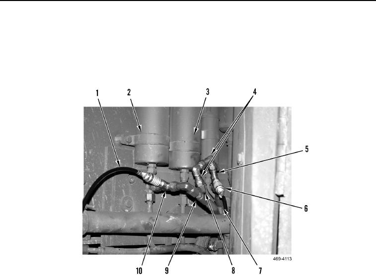
12. Install tee (Figure 41, Item 10) on LH accumulator (Figure 41, Item 2) and install hydraulic hose assembly
(Figure 41, Item 9) and test hose (Figure 41, Item 1) on tee.
13. Install two 90-degree elbow fittings (Figure 41, Item 4), one tee (Figure 41, Item 5), and hydraulic hose
(Figure 41, Item 7) on RH accumulator elbow (Figure 41, Item 2). Tighten elbow fitting.
14. Install test hose (Figure 41, Item 6) on tee (Figure 41, Item 5).
Figure 41. Test Hoses and Tees.
0044