
TM 5-3805-293-23-3
0044
BRAKE ACCUMULATOR CHARGING VALVE TEST AND ADJUST CONTINUED
15. Start engine (TM 5-3805-293-10).
16. Operate machine until at normal operating temperature 140 9F (60 5C).
N OT E
The cut-in pressure must be adjusted first, because changing the cut-in pressure will also
change the cut-out pressure.
17. Pump service brake pedal until pump reaches cut-in pressure. Compare pressure readings in both pressure
gauges. The lowest pressure is cut-in pressure. The minimum pressure is 1,400 50 psi (9,650 345 kPa).
18. If adjustment is necessary, perform following operation:
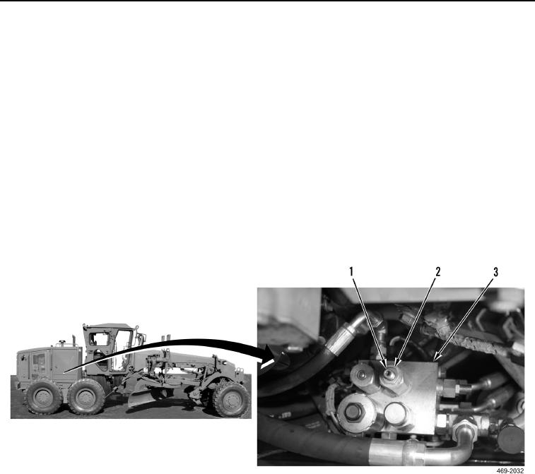
a. Loosen locknut (Figure 42, Item 2) on brake control manifold (Figure 42, Item 3).
b. Turn adjustment screw (Figure 42, Item 1) clockwise to increase cut-in pressure.
c.
Turn adjustment screw (Figure 42, Item 1) counterclockwise to decrease cut-in pressure.
d. Tighten locknut (Figure 42, Item 2) on brake control manifold (Figure 42, Item 3).
Figure 42. Cut-In Pressure Adjustment.
0044