FUEL SYSTEM
TM 5-3805-263-14&P-2
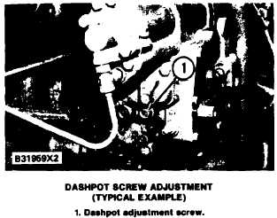
1. Turn dashpot adjustment screw (1) in (clock-
wise) until it stops.
2. Turn dashpot adjustment screw out (counter-
clockwise) 1/2 ± 1/4 turn.
Checking Balance Point
The balance point for the engine is:
1. At 20 rpm higher than full load speed.
2. The point where the power adjustment screw is
against the load stop.
3. The point where the engine has the most horse-
power output.
4. The point where an increase in load on the engine
puts the engine in a lug condition (a condition in
which a small increase in load makes the engine
speed get much less).
Procedure for Checking Balance Point
NOTE: It is important,
to the correct operation of
the transmission, that the BALANCE POINT is
adjusted to the correct specifications.
NOTE: The rack setting must be correct before
an adjustment is made to the balance point.
I. Connect a tachometer which has good accuracy
to the tachometer drive.
TESTING AND ADJUSTING
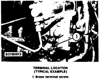
2. Connect a continuity light to the brass terminal
screw (1) on the rear of the governor. Connect
the other end of the light to a place on the fuel
system which is a good electrical ground.
3.
4.
5.
6.
7.
8.
9.
10.
11.
Start the engine.
With the engine at operating conditions, run the
engine at high idle.
Make a record of the speed of the engine at high
idle.
Add load on the engine slowly until the contin-
uity light just comes on. This is the balance
point.
Make a record of the speed at the balance point.
Repeat Step 6 several times to make sure that
the recording is correct.
Stop engine. Make a comparison of the records
from Steps 5 and 7 with the information given
in the FUEL SETTING INFORMATION.
If the full load speed is not correct, adjust the
HIGH IDLE speed to make a change in the full
load speed.
If the high idle speed is out of tolerance and the
full load speed is correct, look for a weak gover-
nor spring or the wrong governor spring. Both
the full load speed and the high idle speed must
be in the tolerance given in the FUEL SET-
TING INFORMATION.
1-56


