AIR INLET AND EXHAUST SYSTEM
TESTING AND ADJUSTING
Valve Seat Inserts
TM 5-3805-263-14&P-2
Tools needed to remove and install seat inserts
are in the 9S3080 Valve Insert Puller Group. For
easier installation, lower the temperature of the in-
sert before it is installed in the head.
Valve Guides
COMPRESSION
An engine that runs rough can have a leak at the
valves, or have valves that need adjustment. Use the
test that follows for a fast and easy method to find a
cylinder that has low compression, or does not have
good fuel combustion. Find the speed that the engine
runs the roughest, and keep the engine at this rpm
until the test is finished. Loosen a fuel line nut at fuel
injection pump to stop the flow of fuel to that cy-
linder. Do this for each cylinder until a loosened fuel
line is found that makes no difference in engine
performance. Be sure to tighten each fuel line nut
after the test before the next fuel line nut is loosened.
This test can also be an indication that the fuel
injection is wrong, so the cylinder will have to be
checked thoroughly. Removal of the head and in-
spection of the valves and valve seats is necessary.
NOTE: The test that follows cannot be used with
engines that have pistons with keystone rings.
A cylinder leakage test that uses air pressure in
the cylinder can be used to indicate the condition
of the piston rings, valves and valve seats. Removal
of the head and inspection of the valves and valve
seats is necessary to find those small defects that do
not normally cause a problem. Repair of these
problems is normally done when reconditioning the
engine.
CYLINDER HEAD
The cylinder head has valves, valve seat inserts,
and valve guides that can be removed when they are
worn or have damage. Replacement of these com-
ponents can be made with the tools that follow:
Tools needed to install valve guides are the 7S8858
Driver Bushing and 7S8859 Driver. The counterbore
in the driver bushing installs the guide to the correct
height. Use a 1P7451 Valve Guide Honing Group to
make a finished bore in the valve guide after in-
stallation of the guide in the head. Grind the valves
after the new valve guides are installed.
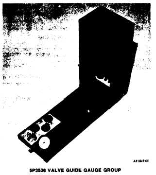
Checking Valve Guide Bore
Use the 5P3536 Valve Guide Gauge Group to
check the bore of the valve guides.
Valves
Valve removal and installation is easier with use of
the 5P1330 Valve Spring Compressor Assembly and
5S1322 Valve Keeper Inserter.
1-59


