AIR INLET AND EXHAUST SYSTEM
TM 5-3805-263-14&P-2
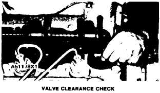
VALVE CLEARANCE
NOTE: Valve clearance is measured between the
rocker arm and the valves.
TESTING AND ADJUSTING
VALVE CLEARANCE CHECK: ENGINE STOPPED
Exhaust............
022 to 028 in. (0.56 to 0.71 mm)
Intake..............
.012 to .018 in. (0.30 to 0.46 mm)
NOTE: When the valve lash (clearance) is checked,
adjustment is NOT NECESSARY if the measure-
ment is in the range given in the chart for VALVE
CLEARANCE CHECK: ENGINE STOPPED. If
the measurement is outside this range, adjustment is
necessary. See the chart for VALVE CLEARANCE
SETTING: ENGINESTOPPED, and make the set-
ting to the nominal (desired) specifications in this
chart.
VALVE CLEARANCE SETTING: ENGINE STOPPED
I n t a k e . . . . . . . . . . . . . . . . . . . . . . . . .015 in. (0.38 mm)
E x h a u s t . . . . . . . . . . . . . . . . . . . . . . . .
.025 in. (0.64 mm)
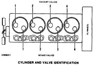
1. Put No. 1 piston at top center (TC) on the
compression stroke. Make reference to FIND-
ING TOP CENTER COMPRESSION POSI-
TION FOR NO. 1 PISTON.
2. Make an adjustment to the valve clearance on
the intake valves for cylinders 1 and 2. Make
an adjustment to the valve clearance on the
exhaust valves for cylinders 1 and 3.
3. Turn the flywheel 360° in the direction of en-
gine rotation. This will put No. 4 piston at top
center (TC) on the compression stroke.
4. Make an adjustment to the valve clearance on
the intake valve for cylinder 3 and 4. Make an
adjustment to the valve clearance on the ex-
haust valves for cylinders 2 and 4.
5. After valve adjustment is correct, tighten the
nuts for the valve adjustment screws to 22 ± 3
lb. ft. (28 ± 4 N•m).
1-60