FUEL SYSTEM
TESTING AND ADJUSTING
TM 5-3805-263-14&P-2
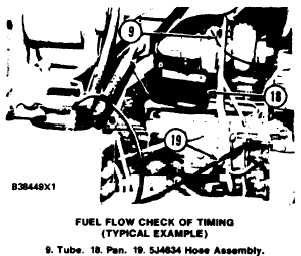
24. To check for correct timing of the fuel system,
make a comparison of the reading on the dial
indicator (3) with the correct measurement in
the chart. Timing must be set within ± 1° of
correct timing angle.
TIMING ANGLE
16°
17°
18°
19°
*20°
* Correct timing angle.
INDICATOR READlNG
3.73 mm
.148 in.
4.20 mm
.165 in.
4.70 mm
.185 in.
5.23 mm
.206 in.
5.79 mm
.228 in.
CHECKING TIMING BY
TIMING PIN METHOD
Tools Needed:
8S2264 Puller Group.
1B3680 Bolts (2) 3/8-24 NF, 95.3 mm (3.75 in.) long.
4B5271 Washer (2).
8B7560 Step Plate.
L1138 Bolt 3/8-24 NF, 12.7 mm (.5 in.) long.
7N1048 Timing Pin.
FT1644 Adapter.
1.
2.
3.
Put No. 1 piston at top center on the com-
pression stroke. Make reference to LOCAT-
ING TOP CENTER COMPRESSION
POSITION FOR NO. I PISTON. Remove
the timing bolt and rotate the crankshaft clock-
wise 30°.
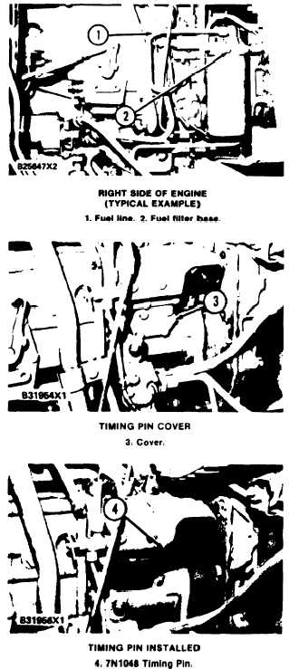
Remove fuel line (I) and fuel filter base (2)
and fuel filter from fuel injection pump hous-
ing.
4. Install 7N1048 Timing Pin (4) in the fuel in-
jection pump housing as shown. Slowly rotate
the crankshaft counterclockwise until timing
pin (4) goes into the groove in the fuel pump
camshaft.
Remove cover (3) from the side of the fuel
injection pump housing.
5. Put the timing bolt in the timing hole in the
flywheel housing. If the bolt can be installed
1-48