POWER TRAIN
TM 5-3805-263-14&P-22
DISASSEMBLY AND ASSEMBLY
DIFFERENTIAL
26.
27.
28.
29.
30.
31.
32.
33.
34.
35.
36.
37.
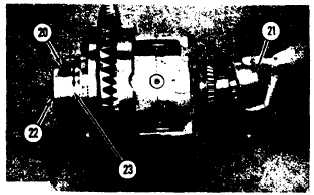
Install the bearing cup and nut (22) in cage
(20). Install ring (23) and the two seals on
the cage.
Put the cage in position over the bearing.
Install the nut and the bearing cup in cage
(21). Put cage (21) in position over the
bearing.
Fasten a hoist and a strap to the differen-
tial. Put the differential in position on the
carrier. Install the ring and seal between the
carrier and cage (20). Make sure the opening
in the cage is in alignment with the ring and
seal.
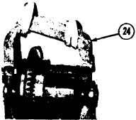
Put cap (24) in position over the studs in
the carrier. Install the dowel in cage (2 1).
Make sure the dowel is in alignment with
the hole in cap (24).
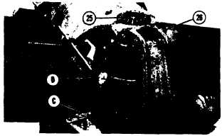
Install nuts (26) that hold the cap to the
carrier. Tighten the four nuts to a torque of
75 lb. ft. (10.4 mkg).
Put the differential in position as shown.
Put tooling (D) in position on the differen-
tial and against a tooth on the bevel gear.
Turn the bevel gear to measure the gear
clearance (backlash) between the pinion and
the bevel gear.
Make an adjustment to nut (22) under the
bevel gear with tool (C), while keeping nut
(26) finger tight against the top bearing, to
get a gear clearance (backlash) of .008 +
.004 - .003 in. (0.20 + 0.10 -0.08 mm).
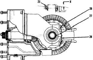
Loosen nut (25). Tighten the nut by hand
to remove the end play. Tighten nut (26) 1
to 1 1/2 notches and measure the amount
of change in dimension (X) with tooling
(D). Dimension (X) must change by .005 ±
.002 in. (0.18 ± 0.05 mm).
Tighten nuts (26) to 280 ± 20 lb. ft. (380
± 27 N•m). Turn the differential and
measure the gear clearance (backlash)
again.
Put locks (27) in position on the cap. Install
the locks and bolts that hold locks (27).
Bend the locks against the bolts. Install
wires (28) through the studs and nuts on
each side of the differential.
Install all the C-ring seals on the differen-
tial.
end by:
a) install differential
2-84.