POWER TRAIN
15.
16.
17.
18.
19.
20.
21.
22.
DISASSEMBLY AND ASSEMBLY
DIFFERENTIAL
TM 5-3805-263-14&P-2
Install the seals on the outside and the
inside of the piston. Install the seals so the
lips are toward the bottom of the bore for
the piston in the piston housing. Put some
clean SAE 30 oil on the lips of the seals.
Install the piston in housing (10).
Heat bearing (9) in oil to a temperature of
275° F (135° C). Install bearing (9) on the
hub of piston housing (10).
Put piston housing (10) and the bevel gear
in position on clutch housing (7). Make sure
the holes in both housings and the bevel
gear are in alignment.
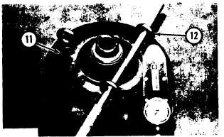
Install three 5/8°-11 NC forged eyebolts
(12) in piston housing (10). Install the bolts
and the washers that hold the piston hous-
ing to the bevel gear and the clutch housing.
Put a bar in position as shown in the
eyebolts. Tighten bolts (11) to a torque of
185 + 10 lb. ft. (25.6 + 1.4 mkg).
Remove the bar and the eyebolts.
Turn the housings and the bevel gear over.
Be careful that gear (6) does not fall out.
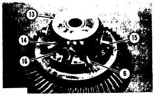
Install the brass bearings in spider gears (14)
with tool (E) and an arbor press.
Install gears (14) and brass washers (16) on
spider (15). Put the spider and the gears in
position on the clutch housing as shown.
NOTE: Make sure the notches in the brass washers
are up.
23. Install gear (13) as shown on the spider
gears. Install the large brass washer on the
face of gear (13). Make sure the hole in the
washer is in alignment with the dowel in the
housing.
24.
25.
Put housing (18) in position on the clutch
housing. Tool (F) can be used to make sure
the notches in washers (16) are in alignment
with the dowels in housing (18). Install
bolts (19) the washers. Tighten the bolts to
a torque of 60 ± 5 lb. ft. (8.3 ± 0.7 mkg).
Heat bearing (17) in oil to a temperature of
275° F (135° C). Install bearing (17) on the
hub of housing (18).
2-83


