POWER TRAIN
TM 5-3805-263-14&P-2
5.
6.
7.
8.
9.
10.
11.
12.
13.
DISASSEMBLY AND ASSEMBLY
DIFFERENTIAL
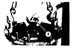
Heat bearing (4) in oil to a temperature of
275oF (135oC).
Install bearing (4) on pinion (1). Make sure
the bearing is in its seat in the bearing cup.
Lift the carrier and remove the block from
under the pinion. Put the carrier on the
floor. Remove tooling (A) from the carrier.
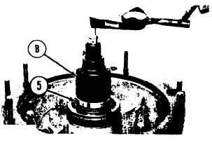
Install the washer, the lock and nut (5) on
the pinion. Do not tighten the nut.
Put two .250 in. (6.35 mm) dowels in the
splines of the pinion. Put the dowels in
position 180o apart. Install tooling (B) over
the pinion and the dowels.
Check the amount of torque needed to
move the pinion without any preload on the
pinion bearings. Remove the torque wrench
from tooling (B).
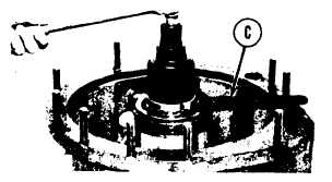
Install a ratchet on tooling (B).
Install tool (C) on nut (5). Tighten nut (5)
with tool (C) while holding the pinion with
the ratchet. Tighten the nut enough to get a
torque of 6 ± 4 lb. in. (6.9 ± 4.6 cm.kg)
more than the torque needed to turn the
pinion when the bearings were not preload-
ed. Remove tooling (B) and (C).
Put clutch housing (7) in position on the
floor as shown. Put a block of wood 2 1/2
in. (63.5 mm) high in the center of the
housing. Put gear (6) in position on the
block.
Put the pressure disc in position in clutch
housing (7). Install the eight discs and the
seven disc assemblies in the housing starting
with a disc.
NOTE: Put clean SAE 30 oil on the discs and disc
assemblies (8) at installation.
14. Put the large brass washer on the face of
gear (6). Make sure the hole in the washer is
in alignment with the dowel in the housing.
2-82


