POWER TRAIN
DISASSEMBLY AND ASSEMBLY
TM 5-3805-263-14&P-2
RELIEF CONTROL VALVE
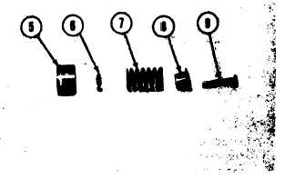
2. Put pin (9) in position in retainer (8). Put
spring (7) and valve (6) in position on the
retainer and pin. Put the side of collar (5)
with a chamfer in position on the valve.
3. Install tool (A) in the collar. Install the
valve in a vise. Put the hole in pin (9) in
alignment with the small holes in the collar.
Install the pin that holds the valve together.
Remove the valve from the vise.
4.
5.
Do Steps 2 and 3 for the other valve.
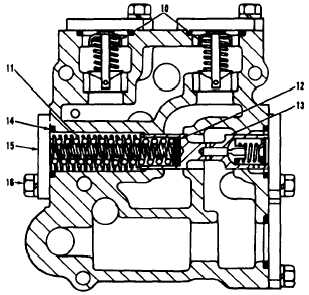
Put spacers (12) in position in valve (13).
Put three springs (11) in position in the
valve.
6. Put the springs and the valve in position in
the valve body.
7. Put valves (10) in position in the valve
body.
8. Install two pins (18) in the valve body.
NOTE: Turn valves (10) to put the hole in the
collar in alignment with pins (18).
9.
10.
11.
12.
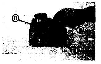
Install the O-ring seal on the plugs. Install
two plugs (17) in the valve body.
Install O-rings (14) in the valve body. Put
five covers (15) in position on the valve
body. Install bolts (16) that hold the covers.
Install the O-ring seals on the back side of
the valve body.
See POWER SHIFT TRANSMISSION
TESTING AND ADJUSTING for making
adjustments to the relief control valve.
end by:
a) install relief control valve
2-66