POWER SHIFT TRANSMISSION
TESTING AND ADJUSTING
TM 5-3805-263-14&P-2
6. Put selector lever (1) in the FORWARD-NEU-
TRAL position.
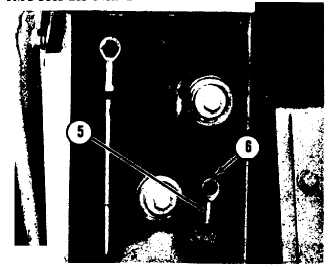
7. Push down on the end of the cable as far as it
will go. If the hole in end (5) is not in
alignment with the hole in lever (6), use the
following procedure:
DIRECTION CONTROL ADJUSTMENT
5. End. 6. Lever.
(a)
(b)
Measure the total distance that the holes
are out of alignment.
Make an adjustment to end (5) until it is
one-half the distance out of alignment.
8.
9.
10.
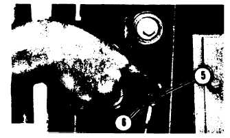
DIRECTION CONTROL ADJUSTMENT
5. End. 6. Lever.
Install the lockwasher and bolt in end (5) and
lever (6).
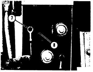
Remove the bolt and lockwasher that holds
the end (7) to the lever (8).
Push down on the end (7) of the cable as far as
it will go (the selector spool will be in SIXTH
speed). Now pull up on the end of the cable
until three detents are felt (detents for SIXTH,
11.
12.
FIFTH, and FOURTH speeds). The selector
spool is now in FOURTH speed.
Put the selector lever (1) in the FOURTH
FORWARD position and be sure the lever is in
the center of the notch.
Make an adjustment to end (7) until the hole
in end (7) is in alignment with the hole in lever
(8).
SPEED CONTROL ADJUSTMENT
7. End. 8. Lever.
13. Install the lockwasher and bolt in end (7) and
lever (8).
14. Check the position of lever (1) in all of the
speeds in FORWARD and REVERSE. Make
another adjustment to end (7) if necessary.
CONTROL CABLE FOR MANUAL
MODULATION VALVE
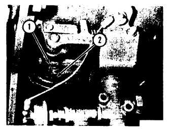
1. Remove the cover for the control housing.
PEDAL FOR MANUAL MODULATION VALVE
1. Block. 2. Pedal.
2-38