POWER SHIFT TRANSMISSION
TESTING AND ADJUSTING
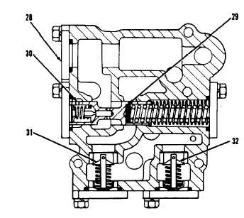
RELIEF VALVE GROUP
28. Relief valve group. 29. Spacars. 30. Main relief valve.
3 1 . R e l i e f v a l v e f o r o i l c o o l e r . 3 2 . R e l i e f v a l v e f o r
transmission lubrication oil.
PRESSURE CHANGE TO THE VALVES
BY REMOVAL OR ADDITION OF ONE SPACER
Spacer
Thickness
Change in
Where
Part No.
in.
mm
psi
kPa
Used
5 M 3 4 9 2
. 0 1 0
0 . 2 5
5 . 4
3 7 . 0
M a i n
7M1397
.036
0 . 9 1
1 9 . 6
1 3 4 . 5
R e l i e f
7M1396
.062
1 . 5 7
3 3 . 7
2 3 1 . 4
V a l v e ( 3 0 )
5 M 3 4 9 2
.010
0 . 2 5
2.01
13.87
Modulating
7M1397
. 0 3 6
0.91
7 . 2 5
5 0 . 0 0
Reducing
7M1396
. 0 6 2
1.57
12.50
8 6 . 0 0
Valve (21)
CLUTCHES ENGAGED
TRANSMISSION
IN TRANSMISSION
SPEED
FORWARD
R E V E R S E
FIRST
SECOND
T H I R D
F O U R T H
F I F T H
SIXTH
NEUTRAL
l, 5, and 6
1, 4, and 6
1, 3, and 6
1, 5, and 7
1, 4, and 7
1, 3, and 7
3 and 7
2, 5, and 6
2, 4, and 6
2, 3, and 6
2, 5, and 7
2, 4, and 7
2, 3, and 7
3 and 7
TM 5-3805-263-14&P-2
3P891 TRANSMISSION OIL PUMP
BENCH TEST SPECIFICATIONS
T y p e . . . . . . . . . . . . . . . . . . . . . . . . . . . . . . . . . . . . . . .
Gear
Number of sections
. . . . . . . . . . . . . . . . . . . . . . . . . . .
T w o
Rotation . . . . . . . . . . . . . . . . . . . . . . . . . . . . . . . .
Clockwise
Output large section:
Using SAE 10W oil at 120°F
( 4 9o ) ] . . . . . . . . . . .
42.5 U.S. gpm (161 litre/min) minimum
A t a s p e e d o f . . . . . . . . . . . . . . . . . . . . . . . .
2200 rpm
A t a p r e s s u r e o f . . . . . . . . . . . . . . . . .
60 psi (415 kPa)
Output small section:
[Using SAE 10W oil at 120oF
(49o C)] . . . . . . . . 23.7 U.S. gpm (90 litre/min) minimum
At a speed of
. . . . . . . . . . . . . . . . . . . . . . . .
2200 rpm
At a pressure of . . . . . . . . . . . . . . . .
325 psi (2250 kPa)
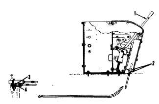
ADJUSTMENT OF CABLES FOR
TRANSMISSION CONTROL
WARNING: Do not make any adjustments
to the cables with the engine running.
Speed and Direction Cables
1. Be sure all of pins (4) for the ends of the
cables are in slots (3) of the valve spools.
2. Make an adjustment to nuts (2) on the ends of
the cable housing so the extension of the
threads on both sides is the same.
SPEED AND DIRECTION CABLE CONTROLS
1. Selector lever. 2. Nuts. 3. Slot. 4. Pin.
3. Put selector lever (1) in the REVERSE-NEU-
TRAL position. Remove the front cover for
the controls.
4. Remove the bolt and lockwasher that holds
the end (5) to the lever (6).
5. Pull up on the end of the cable as far as it will
go. Make an adjustment to end (5) until the
hole in the end is in alignment with the hole in
lever (6).
2-37