SYSTEMS OPERATION
DIFFERENTIAL AND BEVEL GEAR
TM 5-3805-263-14&P-2
DIFFERENTIAL LOCK VALVE
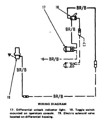
The electric differential control switch (18)
controls a solenoid activated hydraulic valve lo-
cated on the differential carrier. When switch (18)
is in the off (LOCK) position, the indicator light
(17) is off. No current flows to the solenoid coil
connector (16) and the valve is held open by spring
force. P1 pressure oil from the transmission relief
valve group flows through a hose to opening (15).
The internal passages of the solenoid valve act as an
orifice.
When the differential control switch (18) is in
the on (UNLOCKED) position, the indicator light
(17) is on and current flows to the solenoid coil
connector (16). The solenoid force then moves the
valve spool against its spring force. The pressure oil
in cavity (2) goes through opening (11) to the
reservoir. Pinions (7) and side gears (8) and (9) are
now free to turn when traction under each tandem
is different.
The differential with the electric control can be
locked in any speed since the P1 pressure source is
taken direct from the transmission relief valve.
P1 oil goes into opening (15) and out opening
(12) to the differential lock clutch. The oil goes
into the differential through the differential cage
assembly to cavity (2) in the differential housing.
The P1 oil pushes piston (1) against clutch plates
(3) which cause side gear (9) to turn with bevel
gear (4). Pinions (7) do not turn on spider (5) but
turn with side gears (8) and (9).
The speed of the wheels will be equal, even if
the traction under each tandem becomes different.
2-28