TRANSMISSION HYDRAULIC CONTROLS
PILOT SELECTOR VALVE
The function of the pilot selector valve is to
control the movement of the speed selector spools.
This control is done either by sending signal
pressure to the speed selector spool or by letting
the signal pressure in the speed selector spool go to
the reservoir.
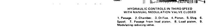
MANUAL MODULATION VALVE
The manual modulation valve lets the operator
control the P2 pressure to the directional clutches
and move the machine a little distance at a time.
The left foot pedal in the operator’s compartment
is connected to the manual modulation valve with
a cable.
The pilot selector valve has two chambers in its
center. Chamber (1) is connected to a passage that
goes to the transmission reservoir. Chamber (2) is
connected to a passage from the priority reducing
valve for signal pressure.
SPEED
PASSAGE WITH SIGNAL PRESSURE
N
A and F
1
B and G
2
B and E
3
B and F
4
G
5
E
6
F
Five more passages connect the speed selector
spools to one of the two chambers in the pilot
selector spool. When the selector spool is in
NEUTRAL, FIRST, SECOND, or THIRD, two of
the passages have signal pressure because they
connect to chamber (2) in these positions. The
other three passages are connected to the transmis-
sion reservoir through chamber (1). When the
selector spool is in FOURTH, FIFTH, or SIXTH,
only one of the passages is connected to chamber
(2) while the other four are connected to chamber
(1).
SYSTEMS OPERATION
TM 5-3805-263-14&P-2
When the left foot pedal is up and the manual
modulation valve is not being used, spool (6) is in
the position shown. P1 pressure from the load
piston (8) goes through passage (7) and is stopped
by the spool (6). P2 pressure goes around piston
(4) and to the direction clutches. P2 pressure also
goes through orifice (3) and into chamber (2)
where the pressure is stopped. P1 and P2 are at
their maximum pressures.
When the left foot pedal is pushed down, spool
(6) is moved out as shown. Passage (7) from the
load piston is connected to passage (1) which lets
P1 pressure oil from the load piston (8) go to the
reservoir. The location of the orifice for passage (7)
at the load piston (8) prevents P1 pressure from
going lower than 90 psi (620 kPa). The clutches are
now operating at a lower pressure.
At the same time that passage (7) is connected
to passage (1), chamber (2) is also connected to
passage (1) which lets P2 pressure oil in the
chamber go to the reservoir, P2 pressure on the
slug (5) moves the piston (4) to the left and causes
2-25