TM 5-3805-263-14&P-3
DISASSEMBLY AND ASSEMBLY
DISCONNECT SWITCH
REMOVE AND INSTALL DISCONNECT
SWITCH
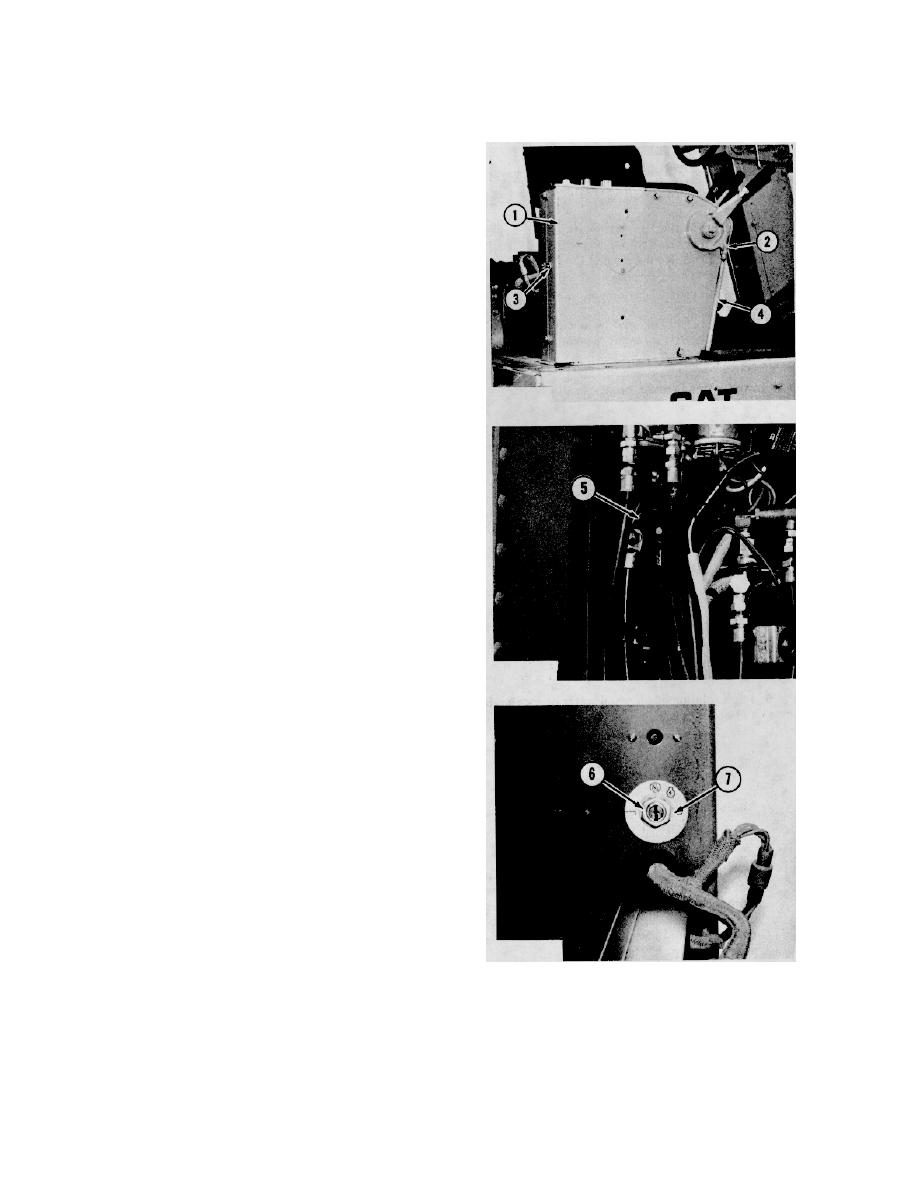
NOTE: The cab was removed for better photo illustration.
1.
Remove the cotter pin and pin (2) from linkage (4).
Move the linkage free of the handle. Remove bolts
(3) and cover (1).
2.
Disconnect battery cable and ground cable from the
back of disconnect switch (5).
3.
Remove nut (6), washer (7) and disconnect switch
from panel.
NOTE: The following steps are for installation of the
disconnect switch.
4.
Put disconnect switch (5) in position and install
washer (7) and nut (6) that hold the disconnect
switch in place.
5.
Connect battery cable and ground cable to the
disconnect switch.
6.
Put cover (1) in position on console.
Install the
bolts (3) that hold it.
7.
Put linkage (4) in position on the handle. Install the
pin (2) that holds it. Install the cotter pin.
4-92


