VEHICLE SYSTEMS
TM 5-3805-263-14&P-3
BLADE LIFT ARMS
INSTALL BLADE LIFT ARMS
Tools Needed
A
B
C
D
7F9540
Puller Assembly
1
1
5P3100
Pump Group
(or electric)
1
1
8S6586
Screw
1
1
1P1835
Pulling Adapter
1
5S7351
Nut
1
1
5F7353
Washer
1
1
1P1837
Pulling Adapter
1
.4S9181
Expander Assembly
1
1P510
Driver Group
1
1.
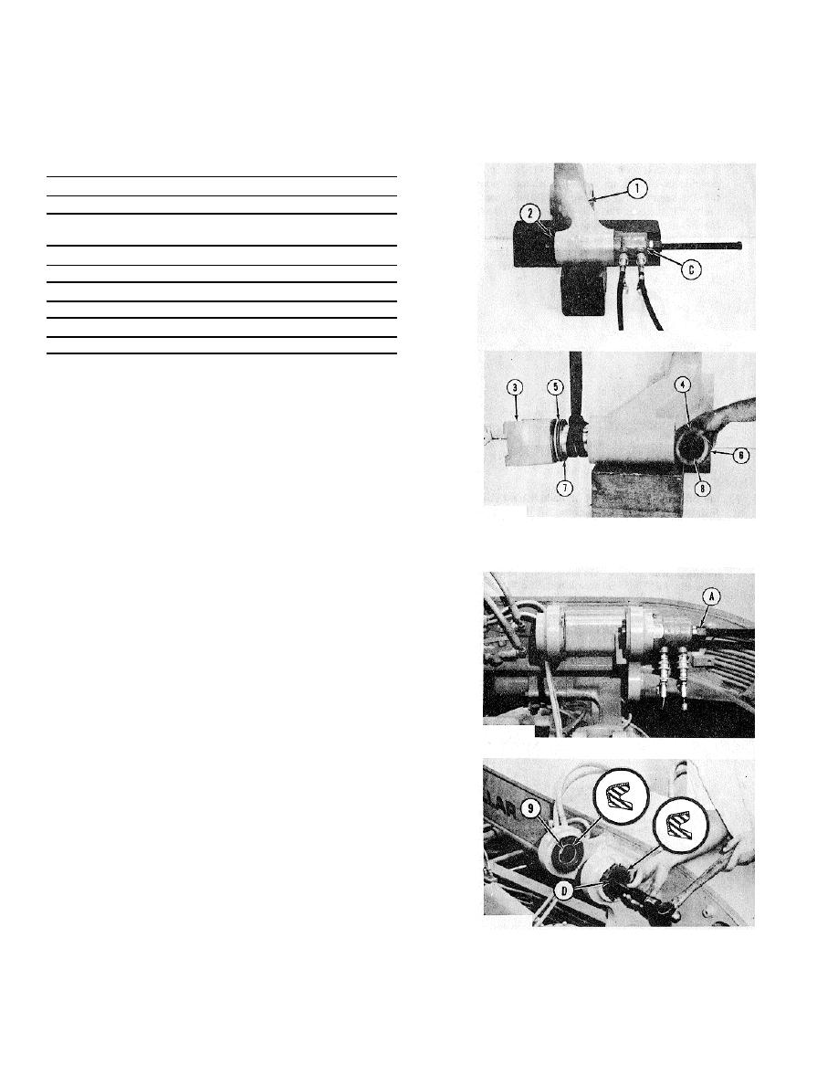
Install the small bearing in blade lift arm (1) with
tooling (A). Install large bearing (2) in the lift arm
with tooling (C). Install the bearings so they make
contact with their respective shoulders.
CAUTION
Tooling (A) and tooling (C) must be used to
install the bearings to prevent damage.
2. Install new seal (5) on yoke (3) with tooling (B).
TYPICAL EXAMPLE
Install washers (7) on the yoke. Fasten a hoist to
yoke (3). Put it in position in the lift arm.
3. Install a new seal on retainer (6). Put shims (8),
washers (4) and the retainer in position on the lift
arm. Install the bolts that hold the retainer to the
yoke. The shims are used to get .01 in. (.25 mm)
maximum end clearance of the yoke. The yoke must
rotate freely in the lift arm.
4. Install new bearings in the frame with tooling (A).
Install the bearings to a depth of .375 + .016 in. (9.53
+ 0.41 mm).
CAUTION: Tooling (A) must be used to install the
bearings to prevent damage.
5. Install four new seals (9) in the frame with tooling
(D). Install the seals with the lip toward the outside
and even with the outside surface.
3-191


