TM 5380-263-14&P-3
VEHICLE SYSTEMS
BLADE LIFT CYLINDERS,
BALL AND SOCKET JOINT INSERTS
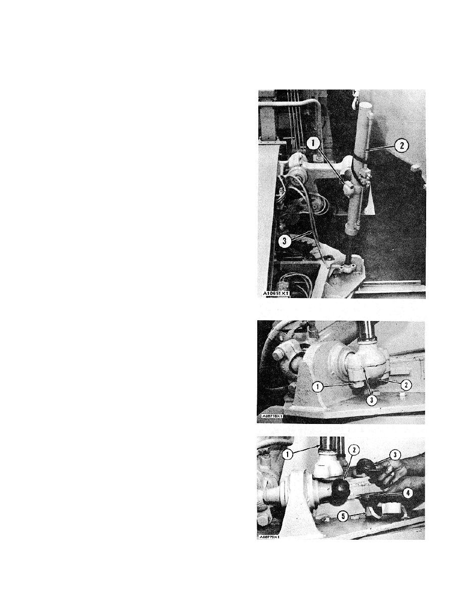
3. Fasten a hoist to the cylinder. Put cylinder (2) in
position on the machine. Install the insert between
the cylinder rod and the ballstud. Install the insert
and the cap. Install the bolts and the lockwashers
that hold the cap to the cylinder rod.
4. Install the four bolts and the lockwashers that hold
caps (1) to the blade lift arm. Tighten the bolts to a
torque of 95 5 lb.ft. (130 7 N.m).
5. Install oil lines (3) to their correct locations on the
cylinder.
6. Repeat Steps 1 through 5 for the other blade lift
cylinder.
REMOVE BALL AND SOCKET
JOINT INSERTS
1. Remove bolts (1) and cap (2) from the blade lift
cylinders or the blade centershift cylinder. Re-
move the insert from cap (2).
2. Start the engine. Move the cylinder rod free of the
ballstud and insert (3). Remove insert (3). Shut off
the engine.
INSTALL BALL AND SOCKET
JOINT INSERTS
1. Put multipurpose grease on the inside surfaces of
inserts (3) and (4) and on ballstud (2).
2. Put new insert (3) in position on ballstud (2). Start
the engine. Move cylinder rod (1) in position on
insert (3) and ballstud (2).
3. Put insert (4) and cap (5) in position under the
ballstud. Install the bolts and washers that hold the
cap to the cylinder rod.
3-189


