TM 5-3805-263-14&P-3
SPECIFICATIONS
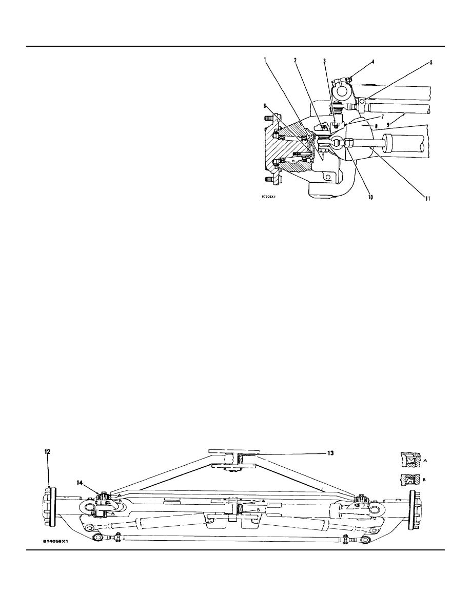
FRONT AXLE (5R6362)
Torque for nut (pin clamp) ................. 515 20 lb. ft.
(1)
(700 25 Nm)
(2)
Torque for nut on ball stud of cylinder
(more torque when needed to
install cotter) ..............100 10 lb. ft. (135 14 Nm)
(3)
Torque for nut on ball stud of tie rod
(more torque when needed to
install cotter) ..............................90 lb. ft. (120 Nm)
(4)
Torque for bolts
(pin clamp) .................185 10 lb. ft. (254 14 Nm)
(5)
Torque for nut
(clamp on tie rod)...............55 5 lb. ft. (75 7 Nm)
Torque for bolts (in spindle) ................... 95 5 lb. ft.
(6)
(130 7 Nm)
Adjustment for the Lengths of the Rods in the Steering
NOTE: Use only one 2G3867 Shim, if necessary, to get 175
Cylinders when the Toe-in for the Front Wheels is Correct:
lb. in. (20 Nm) torque to turn spindle.
(12) Torque for studs ........170 20 lb. ft. (230 25 Nm)
Step 1: Lift. front wheels off ground. Install lockpin in
(13) Use 2G5672 Washers as needed to get 0.06 in.
tie bar.
(1.53 mm) maximum gap.
Step 2: Loosen locknut (10) and turn cylinder rod (11)
(14) Minimum gap between retainers and bar .... 0.03 in.
on to the threads of the ball socket as far as
(0.76 mm)
possible. Do the same with the cylinder rod and
Toe-in for Front Wheels:
ball socket on the right side.
Step 1: Lift front wheels off ground. Install lockpin in tie
Step 3: Steer the wheels for a maximum turn to the left
bar for wheel lean.
and hold steering wheel in this position. Turn
Step 2: Rotate the wheel to put a mark around the
the rod into the steering cylinder on the right
center of the tread on each tire.
side out until the spindle housing stop (7) for
Step 3: Measure the distances from the mark on one
the left wheel contacts the axle assembly stop
tire to the mark on the other tire at both the
(8) across the complete area of the spindle
front and at the rear of the tires. Toe-in is
housing stop (7), then turn the cylinder rod (11)
correct when measurement at the front tires is
for the steering cylinder on the right side out six
0.12 to 0.25 in. (3.0 to 6.3 mm) less than the
complete turns and tighten nut (10).
measure-ment at the rear of the tires.
Step 4: Steer the wheels for a maximum turn to the
Step 4: Make the toe-in adjustment if needed. Loosen
right and hold steering wheel in this position.
nut (5) and the nut in the clamp at the other
Turn rod (11) into the cylinder on the left side
side of tie rod (9). Rotate tie rod (9) in the
out until the spindle housing stop (7) for the
direction needed to get the correct toe-in for the
right wheel contacts the axle assembly stop (8)
front wheels. When the toe-in adjustment is
across the complete area of the spindle
correct, tighten the bolts in the clamps on tie
housing stop (7), then turn the cylinder rod (11)
rod (9).
for the steering cylinder on the left side out six
complete turns and tighten nut (10).
NOTE: Torque for nuts (10) is 250 30 lb. ft. (340 40 Nm).
3-104


