TM 5-3805-263-14&P-3
SPECIFICATIONS
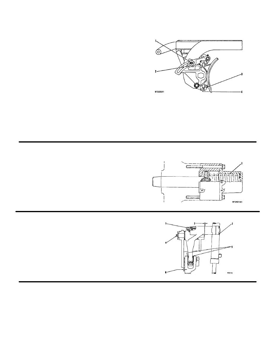
BLADE TIP
Blade Group
(2G6059)
(1) Nut must not be tight Bracket must slide on beam.
(2) Setscrew (six and two).
(3) Setscrew (six).
Adjustment procedure:
Step 1: Lift blade off ground, but do not support the
blade.
Step 2 Turn setscrews clockwise until there is no
free play with
the blade.
Step 3: Loosen setscrews (counterclockwise), '4
turn (90').
NOTE: Setscrews (2) and (3) will not turn (after the
adjustment made) when 9S3263 Thread Lock is
used on the setscrews.
(4) Shims under wear plate. Use shims as needed to
get
clearance between rail and wear plate,
clearance ................ .005 to .035 in. (0.13 to 0.89 mm
CENTERSHIFT LOCK
(8D9920)
(1) 10D4753 Spring
Length under test force .......................... 6 In (152 mm
Test force ...............................286 + 17 lb (1275 + 761
Free length after test .......................8.75 in (222.3 mm
Outside diameter .............................3.625 in (92 1 mm
CENTERSHIFT AND BLADE LIFT
(8D5285)
(1) Shims, use as needed to get end clearance
(2) End clearance (maximum) .........010 in (0 25 mm
(3) Torque for bolts in
yoke clamp ....................95 + 5 lb ft (130 + 7 N-m
(4) Torque for bolt ................95 - 5 lb ft (130 + 7 N-m
(5) Shims use as needed to get clearance between pin
and frame
(6) Clearance between pin and
frame ........................ 09 + 03 in (2.25 + 0 76 mm
3-108


