TM 5-5805-263-14&P-3
HYDRAULIC SYSTEM
AND STEERING
HYDRAULIC CYLINDER DRIFT
Circle Rotation
If tile hydraulic cylinder drift (rods move either in or out of
One fourth of a revolution (90") of the circle is enough
the cylinder when control lever is in HOLD position) is
movement to time. Be sure the blade is in a position
more than .03 in. (0.76 mm) in a time of 5 minutes when
where it will not go against a tire when one fourth
there is a load on the hydraulic cylinder, there is either a
revolution is being made in both directions
component with damage or a component that must be
(counterclockwise and clockwise). The time for the circle
disassembled and cleaned.
to go one fourth of a revolution (in either direction) is 10.5
For an example: There is a load on the lift cylinders
+ I seconds.
when the blade has been lowered enough to move the
If it takes too much time for the circle to go one fourth
front wheels off the ground.
revolution, make a record of the time and the direction
(either clockwise or counterclockwise or both)*.
Causes for cylinder drift.
Steering
1. Damage or defect on cylinder surface.
Make this test while turning the steering wheel at a
2. Seal on piston has damage.
constant rate of one complete turn in one second. Count
3. Scratch or groove in cylinder.
the steering wheel turns (at one revolution in one
4. Scratch or groove on cylinder rod.
second) needed to move the front wheels from a full left
5. Damage on seal in cylinder head.
turn to a full right turn then, from a full right turn to a full
6. Dirt or damage in lock check valve.
left turn. 5 to 6 turns (seconds) will move the wheels
7. Loose fittings or hydraulic lines with damage
from a full turn in one direction to a full turn in the other
that have oil leaks.
direction.
OIL PRESSURE TESTS
A 7S8880 Oil Pressure Gauge (O to 5000 psi), a 5S4648
If it takes too many turns (seconds), make a
Hose Assembly with a 7M1293 Adapter Assembly and a
record of the direction and the turns (seconds)*.
4M5317 Reducing Bushing are used to make these oil
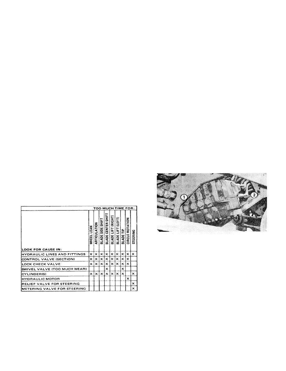
*If the record of time for each operation is too much
pressure tests.
(slow), the implement pump, the combination valve or
both the pump and the combination valve need either an
adjustment or a repair. If the time for only one operation
(other than the steering operation) is correct and the
other operations will not move, or some of the operations
move very slow, the check valve is
CONTROL VALVE ON RIGHT SIDE
1. Plug (into passage for pump oil). 2. Plug (for valve
for control of oil flow, spacers, shims and springs). 3.
Cover (for resolver valve and valve for control of flow). A
1/4 in. hex wrench is used to remove hollow hex plug (1)
to the passage for the pump oil. Install the 7S8880 Oil
Pressure Gauge, the hose and fittings in the plug
opening.
3-21


