TM 5-3805-263-14&P-3
HYDRAULIC SYSTEM
AND STEERING
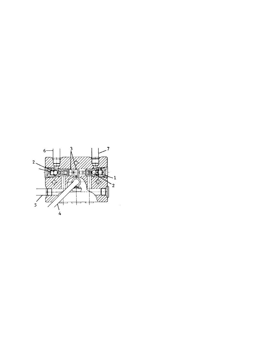
The lock check valves for the cylinders of the blade
tip, the leaning wheel and the side shift do not have
chokes (4) and (5). The operation of the balls and
pistons in these valves is the same as the valves with the
chokes.
The lock check valves for the lift cylinder on the left
side has chokes and a relief valve. The cylinders for the
ripper and scarifier also have lock check valves with
relief valves and chokes. The relief valve is in the
passage to the oil line for the rod end of the cylinder.
There is an increase in the pressure of the oil in the rod
end of the cylinder when a force pulls the rod. When the
force pulling the rod makes the oil pressure in the rod
end of the cylinder go to approximately 4000 psi (281.2
kg/cm2), the relief valve opens. The rod is moved out of
the cylinder until the force pulling on the rod is not
enough to keep relief valve open. The operation of the
balls and piston in this valve is the same as the other
lock check valves.
1. Line to implement valve. 3. Line to implement valve.
8. Line to rod end of cylinder. 10. Line to head end of
cylinder. 11. Relief valve (for rod end).
3-19


