TM 5-3805-263-14&P-3
SYSTEMS OPERATION
Implement Valve in HOLD Position
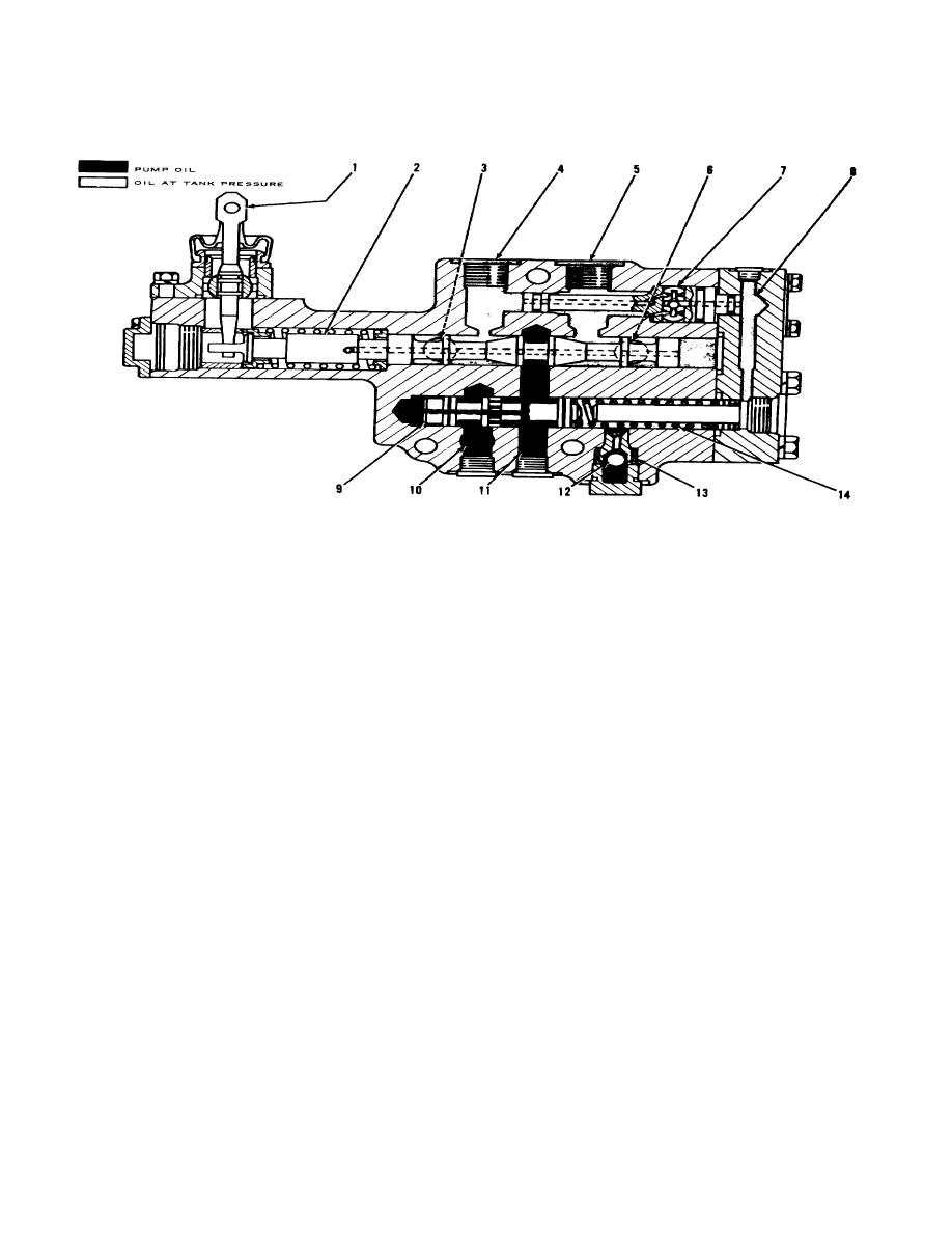
IMPLEMENT VALVE IN HOLD POSITION
1. Lever. 2. Valve spool. 3. Passage to tank. 4. Opening for head end of a cylinder. 5. Opening for rod end of a
cylinder. 6. Passage to tank. 7. Resolver valve. 8. Passage. 9. Valve for control of oil flow. 10. Passage from pump.
11. Passage. 12. Check valve. 13. Passage for oil to shuttle valve in pump. 14. Spring.
The implement valve in HOLD position has pump oil at a
moved to a position where not much pump oil can go
pressure of approximately 2150 psi (151.1 kg/cm2) in the
around valve (9) into passage (II). There is a small
valve when the engine is running.
amount of oil leakage around valve spool (2) in HOLD
position because of the high pressure of the oil in
When the engine is started, the pump oil in passage (10)
passage (11).
goes into passage (11) and then through the holes in
valve (9) to the chamber for the valve that has no spring.
The location of the implement valve puts the valve
The pump oil in passage (11) is stopped by valve spool
lower than the oil in the tank. Oil at tank pressure,
(2) and there is an increase in the pressure of the oil
through passages (3) and (6), is in all passages in the
from the pump. As the pressure of the oil gets higher,
valve that do not have pump oil. Air cannot get into the
the oil pushes valve (9) against the force of spring (14)
implement valve because of the oil in all of the passages
until valve (9) is
in the valve.
3-16


