TM 5-3805-263-14&P-3
TESTING AND ADJUSTING
Check Valve
NOTE: When cover (21) is removed, look for valve (8)
and remove it before it falls out of the valve section.
The check valve that is open is in the valve section
Remove resolver valve (19) by using a No. 8-32 screw
with the highest pressure. When the check valve is open
as a puller.
in one valve section, the pressure of the oil in all of the
other valve sections will be too low.
The edges and surfaces of both the cover and the valve
The plug (15) and the surface of the valve section
section must be clean before the parts and cover are
near the plug must be clean before the plug is removed.
installed. New O-ring seals are used when the parts are
Remove plug (15), spring (13) and ball (12). Use a 3/8 in.
installed in the valve section.
hex wrench in the hex opening in seat and screw (10) to
remove it.
NOTE: The part number for the valve section is on a tab
If the screen has damage or there is a rough seat,
between two bolts through the cover. The tab with the
install a new seat and screen (10). If there is a rough
part number must be installed on the same valve section
surface on ball (12), install a new ball. Use new O-ring
it was on before the bolts and tab were removed.
seals on seat and screen (10), and on plug (15). Torque
for plug (15) is 12 2 lb.ft. (1.7 0.3 mkg).
Control Lever
A control lever (9) that does not move easy needs to
be taken apart and cleaned. Lever (9) should have .006
Valve for Flow Control
.003 in. (0.15 0.08 mm) end clearance. To make an
adjustment for end clearance, loosen boot and nut (7)
A broken spring (17) will not let the pump oil go
and turn screw (11) counterclockwise for more end
through the valve section to the hydraulic cylinder. If it is
clearance. Turn it clockwise for less end clearance. The
necessary to remove valve (8), spring (17) and spacers
torque for boot and nut (7) is 25 lb.ft. (3.5 mkg).
and shims (18), the plug (20) and cover (21) near the
plug must be clean. Use a 3/8 inch hex wrench in the
hex opening in the plug to remove the plug. Spacers and
shims (18) and the spring (17) will fall out of the opening
when plug (20) is removed. The thickness of spacers
and shims (18) control the pressure of spring (17) on
valve (8). The correct thickness spacers and shims were
installed at the factory. When a shim is added to the
spacers and shims, there is a decrease in the time for
the cylinder to operate (the cylinder operates faster).
Oil can keep valve (8) in the valve section. Use a
magnet on the valve if necessary, to remove it. When
the valve, spring, spacers and shims are installed, use a
new O-ring seal on plug (20). The torque for plug (20) is
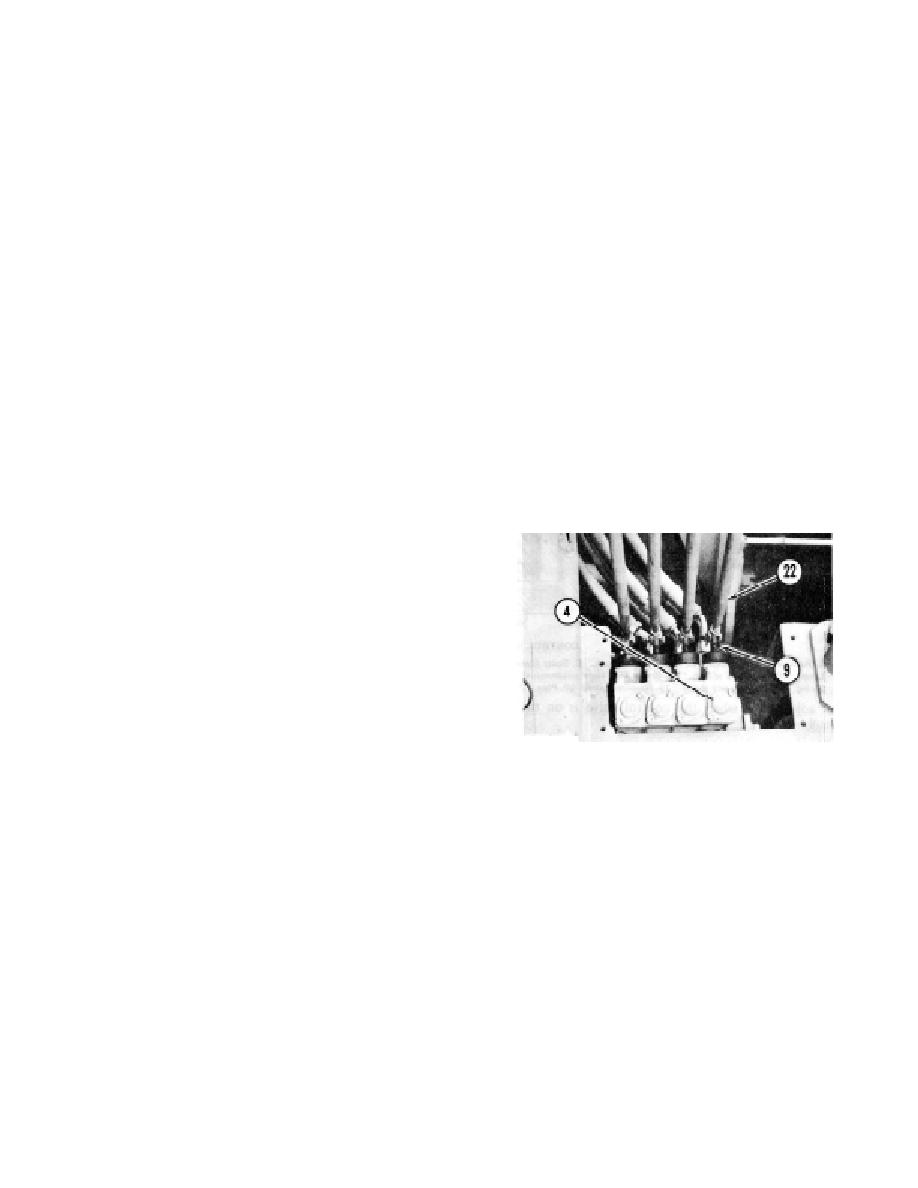
CONTROL VALVE
35 5 lb.ft. (4.8 0.7 mkg).
4. Cap lock (four). 9. Lever (four). 22. Linkage rod (four).
If it is necessary to remove lever (9) and the lever
Resolver Valve
housing for cleaning, first remove the pin from linkage
rod (22) and lever (9).
A resolver valve with damage, is the cause for the
Remove bolts (5), the lever housing, and lever (9) as
speed of either the hydraulic cylinders or the hydraulic
a unit. The O-ring seal and half of bearing (6) will fall out
motor, to be too slow in one direction.
of the lever housing. Lever (9) can be pulled out of boot
Before cover (21) is removed from the control valve
and nut (7), and out the opening in the lever housing that
section, the cover and the control valve near the cover
was against the valve section. Remove the ring with the
must be clean.
seal and the other half of bearing (6).
Remove the eight bolts through cover (21) and
Use new O-ring seals when lever (9) and the lever
remove the cover. It will take force to remove the cover
housing are installed on the valve section. Lever (9) must
from the valve section after the bolts are removed.
have .006 .003 in. (0.15 0.8 mm) end clearance.
3-26


