TM 5-3805-26314&P-3
HYDRAULIC SYSTEM
AND STEERING
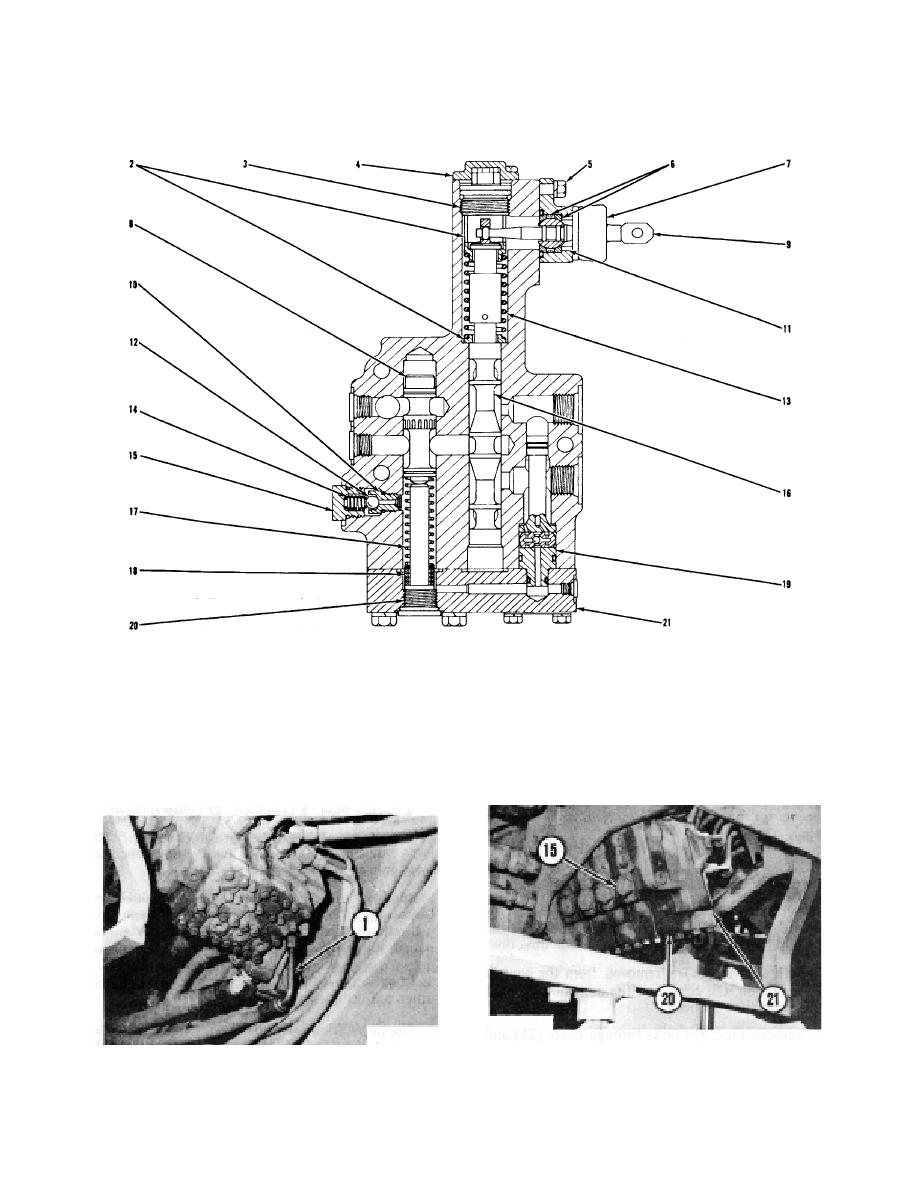
CONTROL VALVE SECTION
2. Retainers (for spring). 3. Plug. 4. Cap lock. 5. Bolts (two). 6. Bearings. 7. Boot and nut. 8. Valve
(control of oil flow). 9. Lever. 10. Seat and screen. 11. Screw (for lever adjustment). 12. Ball. 13.
Spring. 14. Spring. 15. Plug. 16. Valve spool. 17, Spring. 18. Spacers and shims. 19. Resolver valve.
20. Plug. 21. Cover.
an adjustment when the control valve is on the
Disconnect and put a plug in line (1) before removing any
machine.
covers or plugs from the valve section.
Oil, from the hydraulic tank in line (1), can run out
of the control valve when a cover is removed.
CONTROL VALVE (RIGHT SIDE)
CONTROL VALVE
1. Line for oil to hydraulic tank.
15. Plug (four). 20. Plug with 3/8 in. (9.5 mm) hex opening
(four). 21. Cover (four).
3-25


