TM 5-3805-261-34
TRANSMISSION MAINTENANCE
14-6. Transmission Control Relief Valve.
(Sheet 4 of 4)
ASSEMBLY
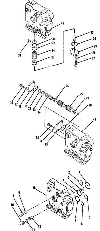
5.
Install two new preformed pack-
ings (30, Figure 14-79) to body.
6.
Install two covers (29), four lock-
washers (28) and bolts (27).
7.
Install poppet (25), spring (24),
retainer (23) and retaining ring (22)
to control relief valve (44, Figure
14-78).
8.
Install spacer (21).
9.
Install new preformed packings
(20 and 19).
10. Install cover (18), two lockwash-
ers (17) and bolts (16).
11. Install cover (15), two lockwash-
ers (14) and bolts (13).
12. Install pin (12), new preformed
packing
(11)
and
plug
(10,
Figure14-77).
13. Install new preformed packing (9)
and plug (8).
14. Install new preformed packings
(7thru 1).
NOTE
Return 130G Grader to original
equipment condition.
Figure 14-79.
Figure 14-78.
Figure 14-77.
End of Task
14-55

