TM 5-3805-261-34
ENGINE MAINTENANCE. (cont)
13-6.
Balancer Shaft Assembly and Bearings. (Sheet 4 of 4)
INSTALLATION (cont)
8.
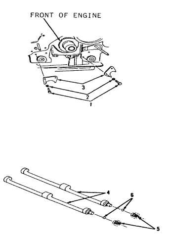
Install two thrust plates (2),
four washers (3) and bolts (1,
Figure 13-32).
9.
Turn two balancer shafts (4)
until the flat part of both
balancer shafts (4, Figure 13-34)
is away from bottom of block.
10. Install two 3/8-16NC bolts 1-1/2
inches long in balancer shafts
(4). This immobilizes balancer
shafts (4).
11. Install oil pump. Refer to
paragraph 3-15.
12. Remove two 3/8-16NC bolts, 1-1/2
inches long.
NOTE
Balancer shaft timing is
correct when holes in shaft
are in alinement with the
holes in oil pan plate and
piston NO. 1 is at top
center compression
position.
Return 130G Grader to
original equipment
condition.
End of Task
13-36
Figure 13-
Figure 13-

