TM 5-3805-261-34
EARTHMOVING EQUIPMENT COMPONENTS MAINTENANCE. (cont.)
12-4. Blade Lift Arm. (Sheet 5 of 5)
INSTALLATION (cont.)
5.
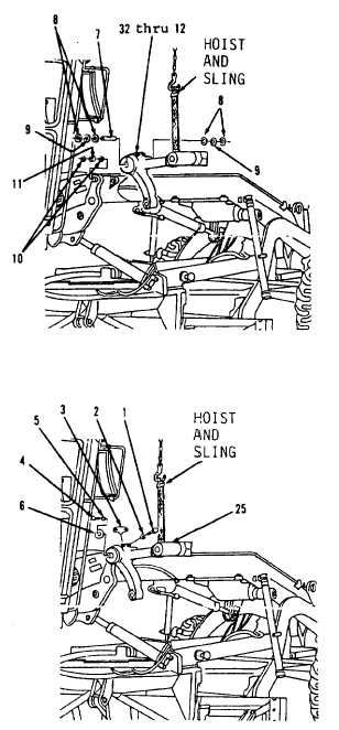
Using tooling given in step 2,
install two new bearings (11) in
center of vehicle frame. Install
two bearings (11, Figure 12-12)
to a depth of 0.359 to 0.391
inch.
6.
Using a driver group, install
four new seals (10). Lips of
four seals (10) must be toward
outside and even with outside
surface.
7.
Attach hoist and sling to items
32 thru 12 as an assembly and
position on frame.
8.
Install items 32 thru 12 as an
assembly, two washers (9), four
washers (8) and pin (7).
NOTE
Groove in pin must be in
alinement with opening in
blade lift arm.
9.
Install plate (6), washer (5) and
bolt (4) on right side blade lift
arm (25, Figure 12-11) only.
10. Install lock (3), two washers (2)
and bolts (1).
11. Remove hoist and sling.
NOTE
Return 13OG Grader to
original equipment condition.
Figure 12-11.
Figure 12-11.
End of Task
12-18

