TM 5-3805-261-34
HYDRAULIC SYSTEM MAINTENANCE. (cont)
10-10.
Hydraulic Control Valves. (Sheet 2 of 11)
DISASSEMBLY
NOTE
The following is a mainte-
nance procedure for the left
valve group. Except for
positioning of valve assem-
blies and manifolds, the
maintenance procedure for the
right valve group is identi-
cal.
1.
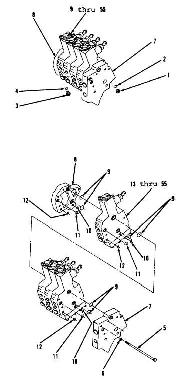
Remove plug (1) and preformed
packing (2) from manifold (7,
Figure 10-77). Discard preformed
packing (2).
2.
Remove plug (3) and preformed
packing (4) from manifold (8).
Discard preformed packing (4).
NOTE
Valve assembly must be
matchmarked if entire valve
group is disassembled to
insure proper placement of
each valve in assembly.
3.
Using scriber, matchmark
manifolds (7 and 8) and items 9
thru 55 as an assembly.
NOTE
The following procedure is
for separation of valve
assembly from a valve group.
The procedure for remaining
valves from the valve group
is identical.
4.
Remove three bolts (5) and
lockwashers (6, Figure 10-78).
Go to Sheet 3
Figure 10-77.
Figure 10-78.
10-58

