TM 5-3805-261-34
BRAKES MAINTENANCE. (cont)
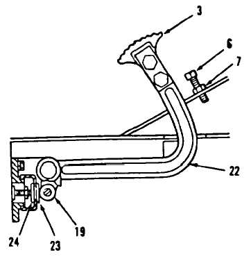
6-8.
Air Brake Control. (Sheet 4 of 4)
ADJUSTMENT (cont)
2.
Turn brake valve plunger adjust-
ment screw (23) after loosening
nut (24), until slight drag is
felt when turning roller (19).
NOTE
Dirt and foreign material
between pedal stop and cab
floor must be removed to
achieve proper pedal adjustment
3.
Turn setscrew (7) all the way
down after loosening nut (6).
4.
Pull pedal (22, Figure 6-17) down
and hold until solid stop is felt
at end of full valve movement.
NOTE
If pedal hits floor before
end of full valve movement,
turn valve plunger adjustment
screw out one full turn.
5.
Turn valve plunger adjustment
screw (24), if necessary.
6.
Turn setscrew (6) out until it
just touches bottom of thread
(3).
7.
Release pedal (22).
8.
Tighten nut (7). Do not turn
setscrew (6) after nut (7) is
tightened.
9.
Tighten nut (23). Do not turn
valve plunger adjustment screw
(24) after nut (23) is tightened.
NOTE
Return 130G Grader to
original equipment condition.
End of Task
6-30
Figure 6-17.