TM 5-3805-261-34
BRAKES MAINTENANCE.
6-8.
Air Brake Control. (Sheet 3 of 4)
INSPECTION
Inspect all parts. Refer to Chapter 2.
INSTALLATION
1.
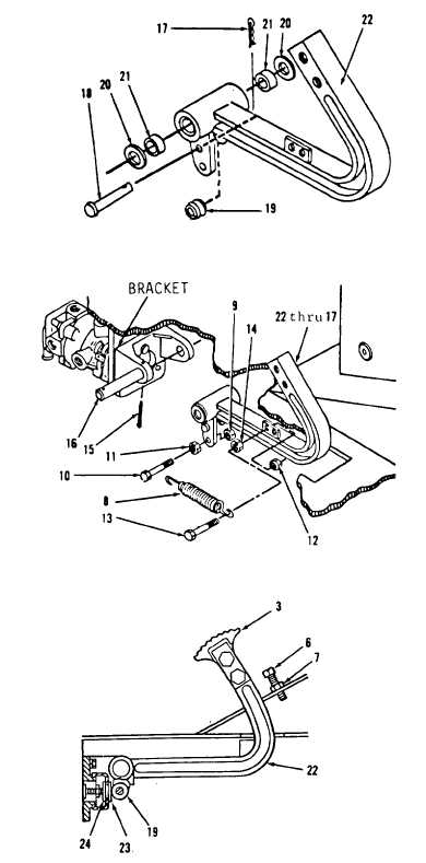
Install two roller bearings (21)
and washers (20, Figure 6-16).
2.
Install roller (19), pin (18) and
new cotter pin (17).
3.
Install items 22 thru 17 as an
assembly, shaft (16) and new
cotter pin (15, Figure 6-15) on
bracket.
4.
Connect governor control linkage.
Refer to paragraph 3-30, step 70.
5.
Install nut (14), bolt (13) and
nut (12).
6.
Install nut (11), bolt (10), nut
(9) and spring (8).
7.
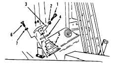
Install nut (7) and setscrew (6,
Figure 6-14) on right side of cab
floor.
8.
Install boot (5), washer (4),
thread (3), two washers (2) and
bolts (1).
ADJUSTMENT
1.
Pump pedal (22, Figure 6-17) on
right side of cab floor to drop
line pressure to zero.
Go to Sheet 4
Figure 6-14.
Figure 6-16.
Figure 6-15.
Figure 6-17.
6-29


