TM 5-3805-261-34
CHARGING SYSTEM MAINTENANCE. (cont)
4-4.
Alternator (Delco). (Sheet 14 of 18)
ASSEMBLY (cont)
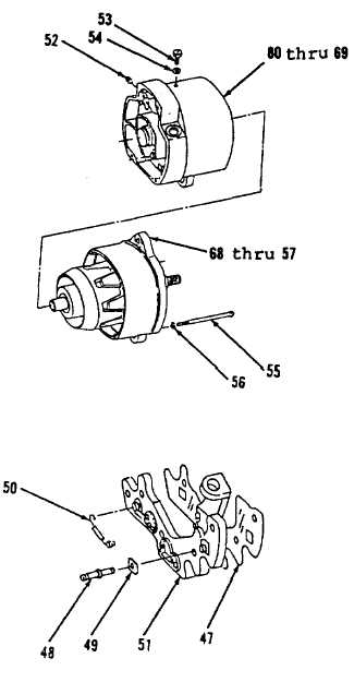
25. Position items 68 thru 57 as an assembly on
items 80 thru 69 as an assembly (Figure 4-7),
alining matchmarks.
26. Install, carefully sliding rotor (57) through stator
(72) onto field coil (75) in housing (80).
27. Install four washers (56) and screws (55).
28. Install lockwasher (54) and screw (53).
29. Install plug (52).
30. Install three positive diode wire assemblies (50,
Figure 4-6), if removed, at terminals. Press into
heat sink (51).
31. Install three insulators (49) and studs (48).
NOTE
The use of silicone grease between insulation and
housing will help promote heat transfer.
32. Using silicone grease, coat insulator (47) lightly.
33. Position insulator (47) on heat sink (51).
Figure 4-7.
Figure 4-6.
Go to Sheet 15
4-18