TM 5-3805-261-34
ENGINE MAINTENANCE. (cont)
3-12. Rocker Arm Assembly. (Sheet 12 of 13)
ADJUSTMENT (cont)
NOTE
The number one cylinder must be at the
compression stroke to obtain proper valve
adjustment.
6.
Check number one cylinder for compression
stroke. Intake and exhaust valves must be
closed. This can be checked by visually
inspecting the valves and by movement in both
rocker arms. If exhaust valve is open, remove
3/8-16NC bolt and turn engine 360 degrees.
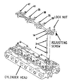
7.
Adjust intake valves for cylinders 1 and 2 on
top of engine. Turn adjusting screws in arms
(14 and 25, Figure 3-63) until a clearance of
0.012 to 0.018 inch is obtained. Secure
screws with lock nuts.
8.
Adjust exhaust valves for cylinders 1 and 3.
Turn screws in arms (9 and 30) until a
clearance of 0.022 to 0.028 inch is obtained
between arms (9 and 30) and push rods (3).
Secure screws with lock nuts.
9.
Remove 3/8-16NC bolt in flywheel before
turning engine.
10.
Turn engine counterclockwise 360 degrees.
Number 4 cylinder should now be at top center
position. Replace 3/8 inch-16NC bolt in
flywheel.
Go to Sheet 13
3-76
Figure 3-63.