TM 5-3805-261-34
HYDRAULIC SYSTEM MAINTENANCE. (cont)
17-3.
Blade Tip Cylinder. (Sheet 4 of 6)
ASSEMBLY (cont)
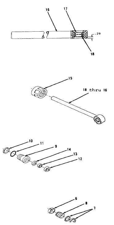
4.
Using bearing driver, install
ring (17) immediately next to new
bearing (18, Figure 17-15).
There should be a depth of 0.29
inch from outer surface of rod
assembly (16) to ring (17).
5.
Remove items 18 thru 16 as an
assembly (Figure 17-13) from
vise.
6.
Position crown (15) on items 18
thru 16 as an assembly (Figure
17-13).
7.
Using clean oil, lubricate new
seals (14 thru 12), new preformed
packing (11) and ring (10, Figure
17-12).
8.
Using seal installer, install new
seals (14, 13 and 12), new
preformed packing (11) and ring
(10) in head (9). Lip of seal
(13) is toward inside of head
(9). Lip of seal (12) is toward
outside of head (9).
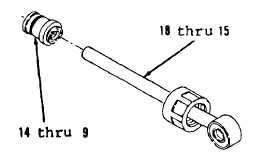
9.
Install items 14 thru 9 as an
assembly on items 18 thru 15 as
an assembly (Figure 17-11).
10.
Using seal expander, install new
seal assembly (7) and ring (6) on
piston (8, Figure 17-10).
Go to Sheet 5
17-10
Figure 17-
Figure 17-10.
Figure 17-
Figure 17-
Figure 17-15.