TM 5-3805-261-34
HYDRAULILC SYSTEM MAINTENANCE.
17-3.
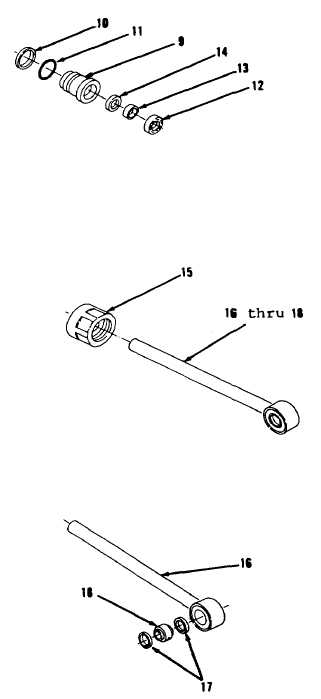
Blade Tip Cylinder. (Sheet 3 of 6)
DISASSEMBLY
8.
Remove ring (10), preformed
packing (11) and seals (12 thru
14) from head (9, Figure 17-12).
Discard preformed packing (11)
and seals (12 thru 14).
9.
Remove crown (15) from items 16
thru 18 as an assembly (Figure
17-13).
10.
Using suitable bearing driver,
remove two rings (17) and bearing
(18) from eye of rod assembly
(16, Figure 17-14). Place rod
assembly (16) in soft jawed vise
and discard bearing (18).
CLEANING
Clean all parts. Refer to Chapter 2.
INSPECTION
Inspect all parts. Refer to Chapter 2.
ASSEMBLY
1.
Position rod assembly (16, Figure
17-14) in soft jawed vise.
2.
Using suitable driver, install
ring (17). Ring (17) is to be
installed to a depth of 0.29 inch
from the outer surface of rod
assembly (16).
3.
Using bearing driver, install new
bearing (18) in rod assembly (16).
Go to Sheet 4
17-9
Figure 17-14.
Figure 17-13.
Figure 17-12.