
TM 5-3805-261-23-2
CIRCLE ASSEMBLY REPLACEMENT - CONTINUED
0344 00
INSTALLATION - CONTINUED
NOTE
Be sure jack stand is not supporting circle when measuring clearance.
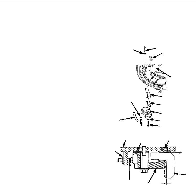
Do not tighten bolts. Use shim(s) as required to obtain 0.020 in. (0.51 mm) maximum clearance
between drawbar, strip, and circle at each shoe.
7.
Install 4 strips (21), 8 strips (14), 28 shims (15), 24
13
12
shims (16), 4 shoes (17), washers (18), bolts (19), 8
14
washers (12), bolts (13), washers (22), and new lock-
nuts (20) on drawbar assembly (2).
8.
Remove sling.
2
15
22
16
17
21
18
19
20
397-1697
9.
With shoes (17) and shims (15) in position on drawbar
2
14
15
assembly (2), adjust four shoes.
10.
Loosen eight nuts (9) on setscrews (10).
9
11.
Tighten setscrews (10) until shoes are against inside of
0.020 IN.
circle (11).
(0.51 MM)
12.
Loosen setscrews (10) until circle (11) is just free to
MAXIMUM
turn.
11
13.
Tighten nuts (9) on setscrews (10).
10
0.031 IN.
17
(0.79 MM)
MAXIMUM97-1699
3
0344 00-5