
TM 5-3805-261-23-2
BLADE LIFT ARM REPLACEMENT - CONTINUED
0341 00
CLEANING AND INSPECTION
Clean and inspect all parts in accordance with WP 0020 00.
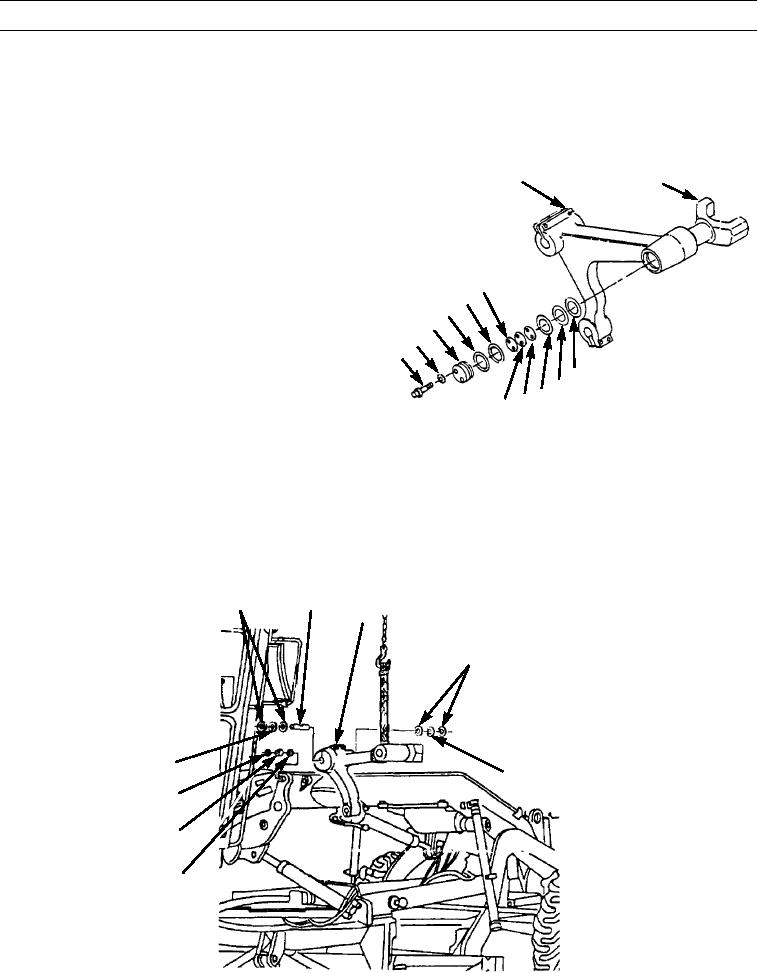
INSTALLATION
1.
Install ring (31), new seals (32 and 33), and washers (28, 29, and 30) on yoke (20). Use expander assembly to install
seals.
NOTE
5
20
Install bearings so contact is made with
shoulders in arm.
2.
Use puller adapter, hydraulic pump, screw, puller
adapter, nut, and washer to install new bearings (26
19
18
and 27) in blade lift arm (5).
17
16
3.
Install yoke (20) in blade lift arm (5).
15
14
4.
Install washers (21, 22, and 23), shims (19, 24, and
21
25), new seals (17 and 18), retainer (16), two washers
23 22
(15), and bolts (14). Use shims (19, 24, and 25) to get
25 24
397-1682
0.01 in. (0.3 mm) maximum end clearance of yoke
(20). Yoke must rotate freely on blade lift arm (5).
5.
Use puller adapter, hydraulic pump, screw, puller adapter, nut, and washer to install two new bearings (13) in center of
machine frame. Install bearings to a depth of 0.359 to 0.391 in. (9.12 to 9.93 mm).
6.
Use bushing driver set to install four new seals (12). Lips of seals must be toward outside and even with outside surface.
7.
Attach sling to blade lift arm (10) and position on frame.
8.
Install blade lift arm (10), two washers (11), four washers (8), and pin (9).
8
9
10
8
11
11
12
13
12
397-1681
0341 00-5