
TM 5-3805-261-23-2
DRAWBAR ASSEMBLY REPLACEMENT - CONTINUED
0342 00
REMOVAL - CONTINUED
5.
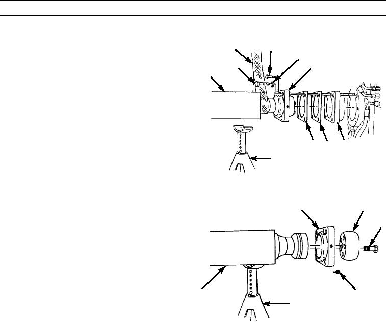
Remove four bolts (9), washers (11), and two bolts
SLING
10
(10) at front of drawbar (1).
11
6.
Slide cap (12) onto drawbar (1).
12
9
1
7.
Lower front of drawbar (1) onto jack stands with sling.
8.
Remove sling.
9.
Remove adapter (13) and shims (14 and 15) from front
corner of drawbar (1).
13
15 14
JACK STAND
397-1687
10.
Remove five bolts (17), ball (16), fitting (18), and cap
12
16
(12) from drawbar (1).
17
1
18
JACK STAND
397-1688
CLEANING AND INSPECTION
Clean and inspect all parts in accordance with WP 0020 00.
INSTALLATION
1.
Install cap (12), fitting (18), ball (16), and five bolts (17) on front cover of drawbar (1).
2.
Measure end play between ball (16) and face of cap (12). Clearance must be 0.0 to 0.02 in. (0.0 to 0.5 mm).
3.
Install shims (14 and 15) and adapter (13).
0342 00-3